Category: Manuals (Page 1 of 6)

leviton humidity sensor manual

Leviton Humidity Sensor Manual: A Comprehensive Guide

This manual provides detailed instructions for Leviton humidity sensors, covering installation, configuration, troubleshooting, and maintenance for optimal performance and efficiency.

Leviton introduced advanced digital sensing technology in January 2014, offering adjustable settings for sensitivity, humidity levels, and automatic time-out features.

Leviton humidity sensors represent a significant advancement in home environmental control, offering automated ventilation solutions for bathrooms, basements, and other moisture-prone areas; Introduced initially in January 2014, these devices utilize state-of-the-art digital sensing technology to proactively manage humidity levels, preventing issues like mold and mildew growth.

These sensors aren’t simply on/off switches; they intelligently respond to changing conditions. Contemporary designs integrate seamlessly into modern homes, while adjustable settings allow customization to specific ventilation needs. Understanding the capabilities of a Leviton humidity sensor is key to maximizing its benefits, ensuring a comfortable and healthy indoor environment, and reducing energy waste.

What is a Leviton Humidity Sensor?

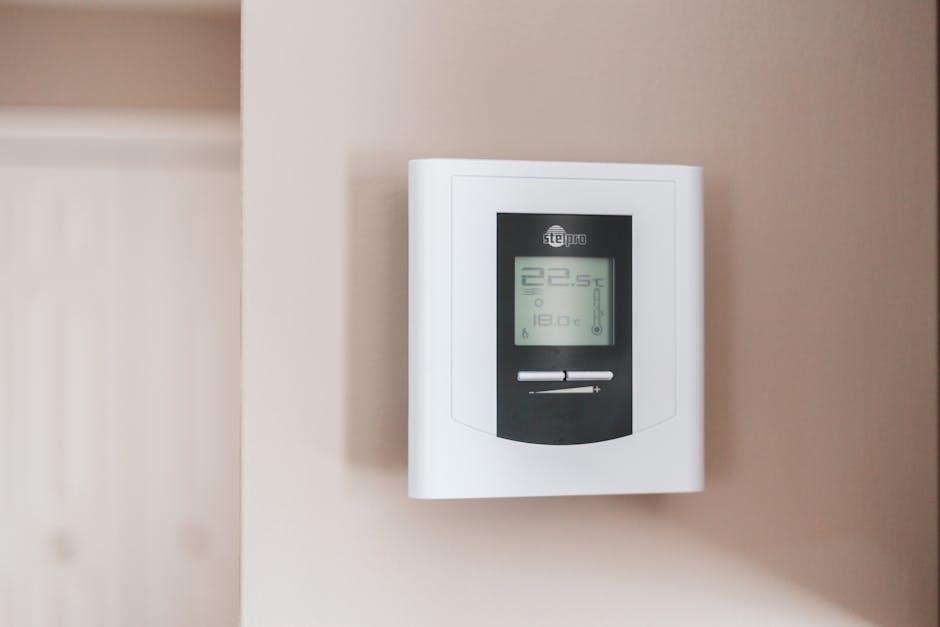
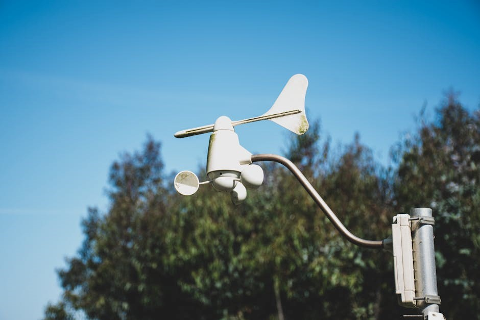
A Leviton Humidity Sensor is an automated device designed to detect moisture levels in the air and activate ventilation, typically an exhaust fan, when humidity exceeds a pre-set threshold. Introduced by Leviton in January 2014, these sensors employ digital technology for precise and reliable readings.

Unlike traditional timers, a humidity sensor responds dynamically to actual conditions, ensuring ventilation only occurs when needed. The device features adjustable sensitivity, humidity level settings, and automatic time-out functions, allowing users to tailor operation to their specific environment. It’s a smart solution for preventing mold, mildew, and maintaining optimal indoor air quality.

Benefits of Using a Humidity Sensor

Employing a Leviton Humidity Sensor offers numerous advantages, primarily centered around improved air quality and resource conservation. These sensors proactively combat mold and mildew growth in moisture-prone areas like bathrooms and basements, safeguarding your home’s structure and inhabitants’ health.

Beyond health benefits, humidity sensors deliver significant energy savings by eliminating the wasteful operation of exhaust fans when they aren’t required. The adjustable settings, including sensitivity and automatic time-out, ensure efficient ventilation tailored to specific needs. This smart technology provides a comfortable and healthy living environment while reducing energy consumption.

Energy Efficiency & Cost Savings

Leviton Humidity Sensors contribute significantly to energy efficiency by intelligently controlling exhaust fan operation. Traditional exhaust fans often run longer than necessary, wasting electricity and increasing energy bills. These sensors activate fans only when elevated humidity levels are detected, preventing unnecessary runtime.

This on-demand ventilation minimizes energy consumption, leading to noticeable cost savings over time. The automatic time-out feature further optimizes efficiency by ensuring fans don’t operate indefinitely after humidity returns to normal. Investing in a Leviton sensor is a practical step towards a more sustainable and economical home environment.

Mold and Mildew Prevention

Maintaining proper ventilation is crucial for preventing mold and mildew growth, particularly in moisture-prone areas like bathrooms and basements. Leviton Humidity Sensors proactively address this concern by automatically activating exhaust fans when humidity levels rise. This rapid response effectively removes excess moisture before it can foster the development of harmful mold and mildew.

By consistently maintaining optimal humidity levels, these sensors contribute to a healthier indoor environment. Preventing mold growth not only protects your home’s structure but also safeguards the well-being of its occupants, reducing allergy and respiratory issues.

Leviton Humidity Sensor Models: Overview

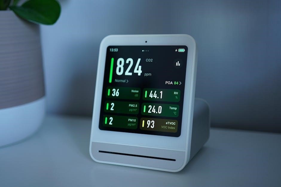
Leviton offers a range of humidity sensor solutions designed to meet diverse ventilation needs. The most prevalent model combines humidity sensing with integrated fan control, providing automated operation for bathrooms and similar spaces. This digital sensor utilizes state-of-the-art technology for precise humidity detection and responsive fan activation.

Beyond the standard digital model, Leviton also provides variations catering to specific applications. These may include sensors with different mounting options, enhanced features, or compatibility with broader smart home systems. Understanding these distinctions allows users to select the optimal sensor for their requirements.

Digital Humidity Sensor & Fan Control (Most Common)

The Leviton Digital Humidity Sensor & Fan Control is a widely adopted solution for automated ventilation. This model employs digital sensing technology to accurately measure humidity levels and automatically activate connected exhaust fans. Its contemporary design seamlessly integrates into various bathroom and basement settings.

Key features include easily adjustable settings for sensor sensitivity, allowing customization based on environmental conditions. Users can also define specific humidity level thresholds to trigger fan operation, and configure an automatic time-out function for efficient energy use. This model represents a balance of functionality and user-friendliness.

Other Leviton Sensor Variations

While the Digital Humidity Sensor & Fan Control is prevalent, Leviton offers alternative sensor solutions to cater to diverse needs. These variations may include models with different mounting options, enhanced features, or compatibility with specific fan types. Some sensors might prioritize energy conservation with more aggressive automatic shut-off timers.

Exploring these options allows for tailored ventilation control. Leviton continually innovates, potentially introducing sensors with smart home integration capabilities or advanced reporting features. Consulting the Leviton catalog or website reveals the full spectrum of available humidity sensing products and their respective specifications.

Installation Guide: Step-by-Step

Proper installation ensures optimal performance and safety. Begin by disconnecting power at the breaker before any wiring. Carefully remove the existing wall plate and disconnect the wires, noting their positions. Connect the Leviton sensor’s wires according to the wiring diagram – typically line, load, neutral, and ground.

Securely mount the sensor to the wall box using the provided screws. Attach the wall plate, ensuring a snug fit. Restore power at the breaker and test the sensor’s functionality. Adjust settings as needed. Always prioritize safety and consult a qualified electrician if unsure.

Safety Precautions Before Installation

Electrical safety is paramount. Always disconnect power to the circuit at the breaker box before commencing any installation work. Verify the power is off using a non-contact voltage tester. Never work with wet hands or in damp environments. Ensure the wiring conforms to local electrical codes and regulations.

If you are uncomfortable working with electrical wiring, consult a qualified electrician. Improper installation can lead to electrical shock or fire hazards. Wear appropriate safety glasses and gloves. Carefully read and understand all instructions before beginning the installation process.

Wiring Diagrams & Electrical Connections

Proper wiring is crucial for safe and effective operation. Typically, the Leviton humidity sensor requires a neutral wire, a line (hot) wire, and a load wire connecting to the fan. Refer to the specific wiring diagram included with your model, as configurations can vary.

Ensure all wire connections are secure using wire connectors approved for the gauge of wire used. Grounding is essential; connect the ground wire to the designated grounding terminal. Double-check all connections before restoring power. Incorrect wiring can damage the sensor or fan.

Mounting the Sensor & Fan Control

Secure mounting ensures accurate readings and reliable operation. Choose a location away from direct water spray, heat sources, and obstructions that could affect airflow. The sensor and fan control unit typically mounts to a standard electrical box.

Use the provided screws to firmly attach the device to the box. Ensure the unit is level for aesthetic appeal and proper functionality. Avoid over-tightening the screws, which could damage the housing. Consider the proximity to the fan for optimal humidity detection and control.

Configuration & Settings Adjustment

Personalize your Leviton humidity sensor for optimal performance. The device features easily adjustable settings, allowing customization to specific ventilation needs. Begin by accessing the configuration menu, typically through buttons or a digital interface on the unit.

Adjust sensor sensitivity to fine-tune detection levels, preventing false triggers or delayed responses. Set humidity level thresholds to define when the fan activates and deactivates. Configure the automatic time-out function to ensure adequate ventilation even after humidity drops.

Adjusting Sensor Sensitivity

Fine-tune the sensor’s responsiveness to humidity changes. Leviton humidity sensors offer adjustable sensitivity settings to prevent unwanted fan activation or delayed responses. Lower sensitivity minimizes false triggers from brief humidity spikes, ideal for areas with frequent steam.

Increase sensitivity for quicker detection in spaces prone to persistent moisture. Experiment with different levels to find the optimal balance for your environment. Refer to the device’s interface or manual for specific adjustment instructions, ensuring accurate and reliable performance.

Setting Humidity Level Thresholds

Establish the humidity percentage that triggers fan activation. Leviton sensors allow users to define specific humidity thresholds, customizing ventilation based on environmental needs. A lower threshold initiates the fan sooner, proactively combating moisture buildup. Conversely, a higher threshold delays activation, suitable for spaces requiring less aggressive ventilation.

Carefully consider the room’s typical humidity levels and desired comfort. Adjust the threshold incrementally to achieve optimal performance, balancing effective moisture control with energy conservation. Consult the manual for precise setting procedures.

Automatic Time-Out Function Configuration

Configure the fan’s runtime after humidity returns to normal. The Leviton sensor’s automatic time-out feature ensures complete moisture removal, even after the initial humidity trigger subsides. Users can set a specific duration – ranging from minutes to hours – for the fan to continue running.

This prevents residual moisture from fostering mold or mildew growth. Adjust the time-out setting based on room size and ventilation effectiveness. Shorter durations conserve energy, while longer durations provide more thorough drying. Refer to the manual for detailed configuration steps.

Troubleshooting Common Issues

Resolve typical problems with your Leviton humidity sensor. If the sensor fails to detect humidity, verify power supply and sensor placement, ensuring it’s not obstructed. A fan not responding indicates wiring issues or incorrect settings; double-check connections and configuration.

Inaccurate readings suggest calibration is needed or the sensor is exposed to extreme temperatures. Consult the manual for specific diagnostic steps. Regularly inspecting wiring and ensuring proper ventilation can prevent many issues. If problems persist, contact Leviton support for assistance.

Sensor Not Detecting Humidity

Troubleshoot why your Leviton sensor isn’t registering moisture. First, confirm the power supply to the unit is active and stable. Ensure the sensor isn’t physically blocked by debris or obstructions hindering airflow. Verify the sensitivity setting isn’t set too high, preventing detection of minor humidity increases.

Check the sensor’s location; it should be positioned to capture ambient humidity, away from direct ventilation. If issues continue, a reset to factory defaults might resolve the problem. Finally, confirm the sensor hasn’t reached its lifespan and requires replacement.

Fan Not Responding to Sensor

Address situations where the fan doesn’t activate upon humidity detection. Initially, double-check all wiring connections between the sensor, fan, and power source, ensuring secure and correct placement. Confirm the fan itself is functioning correctly by manually testing it, bypassing the sensor control. Verify the humidity threshold is set appropriately – too high a setting won’t trigger the fan.

Inspect the automatic time-out setting; it might be overriding the sensor’s signal. A reset of the sensor could resolve communication errors. If problems persist, the fan motor may be faulty.

Incorrect Humidity Readings

Troubleshoot inaccurate humidity level displays from your Leviton sensor. Begin by ensuring the sensor isn’t directly exposed to water splashes or excessive condensation, as this can skew readings. Check for nearby heat sources or drafts that might influence the sensor’s environment. A simple reset of the device can often recalibrate the internal sensors.

If the issue continues, verify the sensor’s location isn’t affected by poor air circulation. Periodic calibration, as outlined in the maintenance section, may be necessary for sustained accuracy.

Maintenance & Care

Ensure long-lasting performance of your Leviton humidity sensor with routine upkeep. Regularly clean the sensor’s exterior with a soft, dry cloth to remove dust and debris, avoiding any liquids. Implement periodic checks – at least twice a year – to verify accurate humidity readings and fan responsiveness.

Consider calibration, if readings seem off, following the configuration instructions. Inspect wiring connections for tightness and corrosion. Proper maintenance safeguards against malfunctions and extends the sensor’s lifespan, maintaining optimal air quality control.

Cleaning the Sensor

Maintaining a clean sensor is crucial for accurate readings and reliable operation. Always disconnect power before cleaning. Use a soft, dry cloth to gently wipe the sensor’s exterior, removing dust and any accumulated grime. Avoid using water, cleaning solutions, or abrasive materials, as these can damage the sensitive components.

For stubborn debris, a can of compressed air can be used cautiously. Ensure the air stream isn’t too forceful. Regular cleaning, ideally every few months, prevents build-up that could obstruct airflow and affect performance.

Periodic Checks & Calibration

To ensure continued accuracy, perform periodic checks of your Leviton humidity sensor. Compare readings to a calibrated hygrometer at least twice a year. If discrepancies exist, slight adjustments to the sensor’s settings might be necessary, though full calibration typically isn’t user-accessible.

Monitor the sensor’s responsiveness to humidity changes. If it seems sluggish or inaccurate, review the installation and configuration. Consistent issues may indicate a need for professional servicing or replacement. Regular monitoring helps maintain optimal performance.

Leviton Humidity Sensor Specifications

Leviton humidity sensors are designed for standard 120V AC power systems. While specific power consumption varies by model, it’s generally minimal, contributing to energy efficiency. The sensors typically operate within a humidity range of 20% to 95% relative humidity, with an accuracy of ±5%.

These devices are built for indoor use and should not be exposed to direct moisture or extreme temperatures. Refer to the individual model’s datasheet for precise specifications, including dimensions and operating temperature ranges. Warranty details are outlined separately;

Power Requirements

Leviton humidity sensors and fan controls are universally designed to operate on a standard 120-volt AC power supply. These devices do not require batteries for operation, relying solely on the connected electrical circuit. Ensure the circuit is properly grounded and meets local electrical codes before installation.

Power consumption is relatively low, contributing to overall energy savings. Specific wattage requirements will vary slightly depending on the model and whether a fan is actively running. Always disconnect power at the breaker before any wiring or maintenance procedures.

Humidity Range & Accuracy

Leviton humidity sensors are engineered to accurately detect moisture levels within a broad range, typically spanning from 20% to 95% Relative Humidity (RH). This wide range ensures effective operation in diverse environments like bathrooms and basements.

Accuracy is generally maintained within ±5% RH, providing reliable data for automated fan control. However, extreme temperatures or direct water exposure can temporarily affect readings. Regular calibration, as outlined in the maintenance section, helps maintain optimal precision and consistent performance over time.

Warranty Information & Support

Leviton stands behind its humidity sensors with a limited warranty, typically covering defects in materials and workmanship for a period of one to two years from the date of purchase. Please retain your proof of purchase for warranty claims.

For technical support, troubleshooting assistance, or to locate authorized service centers, visit the Leviton website or contact their customer service department. Detailed product information, FAQs, and downloadable resources are readily available online. Leviton’s commitment ensures a positive user experience and lasting product satisfaction.

exmark lazer z e series manual

Exmark Lazer Z E Series Manual: A Comprehensive Guide

This detailed guide provides essential operating‚ maintenance‚ and safety instructions for the Exmark Lazer Z E Series‚ ensuring peak performance and longevity.

Congratulations on selecting an Exmark Lazer Z E Series mower! This machine represents a significant investment in professional-grade landscaping equipment‚ meticulously engineered for durability and exceptional cutting performance. This series is renowned for its robust construction‚ powerful engines‚ and innovative features designed to maximize operator comfort and efficiency.

This manual serves as your primary resource for understanding the intricacies of your mower. Within these pages‚ you’ll find comprehensive guidance on safe operation‚ routine maintenance‚ and troubleshooting procedures. Familiarizing yourself with this information will not only ensure optimal performance but also extend the lifespan of your valuable equipment. Exmark is committed to providing reliable products and dedicated customer support.

Understanding the Importance of the Manual

This operator’s manual isn’t simply a collection of instructions; it’s a vital tool for safeguarding your investment and ensuring years of reliable service from your Exmark Lazer Z E Series mower. Thoroughly understanding the content minimizes the risk of damage‚ costly repairs‚ and potential injury.

Detailed within are crucial safety precautions‚ proper operating techniques‚ and a comprehensive maintenance schedule. Adhering to these guidelines will optimize performance and uphold the integrity of the machine. Access to downloadable PDF versions and readily available service contacts further enhance usability. Ignoring the manual’s recommendations may void warranty coverage.

Safety Precautions & Operational Guidelines

Prioritize safety by carefully reviewing all precautions and operational procedures before using your Exmark Lazer Z E Series mower for optimal results.

General Safety Rules

Always disconnect the spark plug wires before performing any maintenance or adjustments to prevent accidental starting. Never operate the mower if you are tired‚ ill‚ or under the influence of drugs or alcohol. Ensure all safety shields and guards are properly installed and in good working condition. Keep bystanders‚ especially children and pets‚ away from the operating area. Inspect the mowing area for obstacles that could be thrown by the blade. Wear appropriate personal protective equipment‚ including eye protection and sturdy footwear. Avoid loose clothing that could become entangled in the machinery. Be aware of your surroundings and operate the mower responsibly. Never attempt to override or disable any safety features. Follow all local safety regulations and ordinances.

Pre-Operational Checks

Before each use‚ check the oil level and add if necessary‚ ensuring the correct type is used. Inspect the fuel level and replenish with fresh gasoline‚ avoiding spills. Examine the blades for sharpness and damage‚ replacing or sharpening as needed. Verify that all nuts and bolts are tightened securely. Check tire pressure and adjust to the recommended PSI. Inspect the hydraulic system for leaks and proper fluid levels. Ensure the safety interlock switches are functioning correctly. Confirm the discharge chute is clear of obstructions. Test the engine shut-off switch. Finally‚ visually inspect the entire machine for any unusual wear or damage.

Starting and Stopping Procedures

To start‚ ensure the parking brake is engaged and the blades are disengaged. Turn the ignition key to the “on” position and allow the system to self-check. Depress the safety interlock button and slowly move the throttle to the start position. Release the key once the engine starts. To stop‚ slowly move the throttle to the idle position. Engage the parking brake. Disengage the blades. Turn the ignition key to the “off” position. Remove the key to prevent unauthorized use. Allow the engine to cool before storing or performing maintenance.

Operating Techniques for Optimal Performance

For best results‚ maintain a consistent ground speed and blade engagement. Avoid sudden turns or stops‚ which can damage the turf. Overlap each cutting pass slightly to prevent scalping. Adjust the deck height to suit the terrain and grass type. Monitor engine temperature and fuel levels during operation. Reduce speed when operating on slopes or uneven ground. Regularly inspect the blades for sharpness and damage. Proper technique extends machine life and delivers a professional-quality cut. Remember safety interlocks must be functional at all times.

Maintenance Schedule & Procedures

Consistent upkeep‚ following daily‚ weekly‚ monthly‚ and seasonal tasks‚ ensures optimal performance and extends the life of your Exmark Lazer Z E Series.

Daily Maintenance Checklist

Before each use‚ a quick daily inspection is crucial for maintaining your Exmark Lazer Z E Series. Begin by visually checking for any loose fasteners or damaged components. Ensure the oil level is adequate and top off if needed. Inspect the air filter for debris and clean or replace as necessary.

Furthermore‚ verify tire pressure is correct for optimal handling and cutting performance. Check the fuel level and replenish as required‚ using fresh fuel to prevent engine issues. Finally‚ briefly inspect the deck for any accumulated grass clippings or obstructions that could affect cutting quality.

Adhering to this simple checklist will contribute significantly to the longevity and reliable operation of your mower.

Weekly Maintenance Tasks

Expand upon daily checks with weekly tasks for sustained performance of your Exmark Lazer Z E Series. Thoroughly clean the engine cooling fins to prevent overheating. Inspect the drive belt for wear and tear‚ replacing if cracked or frayed. Check and grease all lubrication points‚ including wheel bearings and steering components.

Additionally‚ examine the blade for sharpness and balance; sharpen or replace as needed for a clean cut. Clean the underside of the deck‚ removing accumulated debris that can hinder airflow. Inspect hydraulic hoses for leaks or damage‚ addressing any issues promptly;

Consistent weekly maintenance ensures optimal operation and prevents costly repairs.

Monthly Maintenance Requirements

Beyond weekly routines‚ monthly maintenance deepens the care for your Exmark Lazer Z E Series. Inspect the air filter and replace it if dirty‚ ensuring optimal engine performance. Check the fuel filter and lines for contamination‚ replacing as necessary to prevent fuel delivery issues.

Furthermore‚ examine the hydraulic fluid level and condition‚ topping off or changing it according to the manual’s recommendations. Inspect all fasteners and tighten any that are loose‚ preventing vibrations and potential damage. Check the tire pressure and adjust to the manufacturer’s specifications.

Proactive monthly checks contribute to long-term reliability.

Seasonal Maintenance & Storage

Preparing your Exmark Lazer Z E Series for seasonal storage is crucial. Before long-term storage‚ stabilize the fuel or drain the fuel tank completely to prevent fuel degradation. Change the engine oil and filter‚ ensuring fresh lubrication for the next season. Inspect and clean the cooling fins on the engine to maintain efficient operation.

Additionally‚ grease all lubrication points‚ protecting moving parts from corrosion. Disconnect the battery and store it in a cool‚ dry place. Cover the mower to shield it from the elements‚ and store it in a sheltered location.

Proper storage safeguards against winter damage.

Component Overview & Identification

This section details key components of the Exmark Lazer Z E Series‚ including the deck‚ engine‚ hydraulic‚ and electrical systems‚ for effective maintenance.

Deck Components & Adjustments

The cutting deck is a critical assembly on your Exmark Lazer Z E Series mower. Key components include the deck shell‚ blades‚ spindles‚ and leveling links. Understanding these parts is vital for optimal cutting performance and deck longevity.

Proper blade installation and balancing are essential to minimize vibration and ensure a clean cut. Regularly inspect blades for wear and damage‚ replacing them as needed. Adjusting the deck leveling ensures an even cut across the entire width of the deck‚ preventing scalping or uneven grass height.

Leveling links allow for precise deck height adjustments. Refer to the manual for specific instructions on adjusting these links to achieve the desired cut height and maintain a level deck position. Consistent maintenance of these components will maximize the life and performance of your mower’s cutting system.

Engine Specifications & Maintenance

Your Exmark Lazer Z E Series is powered by a robust engine‚ with specifications varying by model. Common engine features include horsepower ratings‚ cylinder displacement‚ and fuel capacity. Regularly checking the engine oil level is crucial for preventing wear and ensuring optimal performance.

Air filter maintenance is also vital; a clean air filter ensures proper airflow to the engine. Replace the air filter according to the schedule outlined in the manual. Spark plug inspection and replacement contribute to efficient combustion and reliable starting.

Fuel system maintenance‚ including fuel filter replacement‚ prevents contaminants from reaching the engine. Always use fresh fuel and consider a fuel stabilizer for extended storage periods. Adhering to these maintenance practices will prolong engine life.

Hydraulic System Overview

The Exmark Lazer Z E Series utilizes a sophisticated hydraulic system for smooth and responsive operation of the deck and steering. This system relies on hydraulic fluid to transmit power‚ enabling precise control and maneuverability. Regularly inspect the hydraulic fluid level and check for leaks around hoses‚ fittings‚ and the pump.

Maintaining proper fluid levels is critical for preventing damage to the hydraulic components. Use only the recommended hydraulic fluid specified in the manual. Periodically check the hydraulic filter and replace it as needed to ensure fluid cleanliness;

Inspect hydraulic hoses for wear and tear‚ replacing any damaged hoses immediately. Proper hydraulic system maintenance ensures efficient operation and extends the life of the machine.

Electrical System Diagram

The Exmark Lazer Z E Series electrical system powers the engine start‚ blade engagement‚ and various safety features. A detailed wiring diagram‚ found within the full operator’s manual‚ illustrates the connections between the battery‚ starter solenoid‚ ignition switch‚ and other components.

Understanding this diagram is crucial for diagnosing and repairing electrical faults. Always disconnect the battery before performing any electrical work to prevent accidental shorts or shocks. Inspect wiring harnesses for damage‚ ensuring connections are clean and secure.

Fuses protect the electrical circuits; replace any blown fuses with the correct amperage rating. Refer to the diagram for fuse locations and circuit identification.

Troubleshooting Common Issues

This section details solutions for engine problems‚ deck issues‚ hydraulic system faults‚ and electrical concerns‚ aiding in quick diagnosis and repair.

Engine Problems & Solutions

Addressing engine issues promptly is crucial for maintaining optimal performance. Common problems include difficulty starting‚ often due to a clogged air filter or stale fuel; ensure these are checked regularly. If the engine fails to start‚ verify the fuel shut-off valve is open and the spark plug is clean. For overheating‚ inspect the cooling fins for debris and confirm adequate oil levels.

Low oil pressure requires immediate attention; stop the engine and investigate the cause. Rough running can indicate carburetor issues or a faulty spark plug. Consult the manual for specific troubleshooting steps related to your engine model. Regular maintenance‚ including oil changes and spark plug replacements‚ prevents many engine problems. Always disconnect the spark plug wire before performing any engine maintenance for safety.

Deck Issues & Repairs

Maintaining the deck is vital for a clean and even cut. Common issues include uneven cutting‚ often caused by dull or damaged blades; sharpen or replace them as needed. Check for bent or damaged deck components‚ which can affect cutting quality and safety. Ensure proper deck leveling; refer to the manual for adjustment procedures.

Belt slippage or breakage requires immediate attention; inspect belt tension and replace worn belts. Address any rust or corrosion promptly to prevent further damage. Regularly clean the underside of the deck to remove grass clippings and debris. Always disconnect the spark plug wire before performing any deck maintenance. Consult the manual for specific deck component diagrams and repair instructions.

Hydraulic System Troubleshooting

Addressing hydraulic issues requires careful attention. Low hydraulic fluid levels are a common problem; check and top off with the recommended fluid. Inspect hoses and fittings for leaks‚ replacing damaged components immediately. Listen for unusual noises‚ such as whining or hissing‚ which may indicate a pump issue.

Check the hydraulic filter regularly and replace it as needed to maintain fluid cleanliness. Slow or erratic movement can signal a failing pump or valve. Always relieve hydraulic pressure before disconnecting any lines. Consult the manual’s hydraulic system diagram for component locations and troubleshooting steps. Professional service is recommended for complex repairs.

Electrical System Faults & Fixes

Electrical problems can range from simple to complex. Check the battery connections for corrosion and ensure a full charge. Inspect fuses for blows and replace them with the correct amperage rating. Examine wiring harnesses for damage‚ loose connections‚ or shorts. A non-starting engine could indicate a faulty solenoid or ignition switch.

Use a multimeter to test for voltage and continuity. Refer to the electrical system diagram in the manual for component locations and wiring schematics. Disconnect the spark plug wire before working on the electrical system. Professional assistance is advised for diagnosing and repairing intricate electrical faults.

Warranty Information & Service

Exmark offers a 2-year commercial and 4-year consumer limited warranty on the Lazer Z E Series‚ covering defects in materials and workmanship.

Warranty Coverage Details (2-Year Commercial/4-Year Consumer)

The Exmark Lazer Z E-Series is backed by comprehensive warranty coverage tailored to usage. Commercial applications receive a 2-year limited warranty‚ protecting against defects in materials and workmanship during professional use. For residential or consumer applications‚ a more extensive 4-year or 500-hour limited warranty applies – whichever comes first.

This warranty encompasses all defects arising from normal use‚ ensuring peace of mind. However‚ it doesn’t cover issues stemming from misuse‚ accidents‚ alterations‚ or lack of proper maintenance. Exmark Warranty Company and Exmark Mfg. Co. Inc. jointly administer this warranty‚ providing repair or replacement options at their discretion. Detailed terms and conditions are available within the full warranty statement.

Locating Authorized Exmark Service Dealers

To ensure your Exmark Lazer Z E-Series receives expert maintenance and warranty service‚ utilizing an authorized dealer is crucial. Exmark maintains a widespread network of certified service centers equipped with trained technicians and genuine Exmark parts.

The most efficient way to locate a dealer near you is through the official Exmark website. Their dealer locator tool allows you to search by zip code‚ city‚ or state‚ providing contact information‚ addresses‚ and service capabilities. Choosing an authorized dealer guarantees quality repairs‚ adherence to Exmark standards‚ and valid warranty support. Avoid unauthorized repairs‚ as they may void your warranty coverage.

Understanding Warranty Claim Procedures

Filing a warranty claim for your Exmark Lazer Z E-Series requires adherence to specific procedures to ensure a smooth process. First‚ retain all documentation‚ including the purchase date‚ model number‚ and a detailed description of the issue.

Warranty service must be performed by an authorized Exmark dealer; Contact a local dealer to schedule an inspection and diagnosis. They will assess the problem and determine if it’s covered under warranty. The dealer will then submit the claim on your behalf‚ requiring your original proof of purchase. Exmark Warranty Company reviews claims and authorizes repairs or replacements.

Exmark Warranty Company Contact Information

For direct assistance with warranty inquiries or claim status‚ contacting Exmark Warranty Company is crucial. You can reach them through their official website‚ www.Exmark.com‚ where a dedicated warranty section provides FAQs and contact forms.

Alternatively‚ you can connect with their customer support team via phone. While a specific direct number isn’t widely publicized‚ navigating the Exmark website will lead you to the appropriate contact channels; Ensure you have your model number and purchase information readily available when contacting them. Prompt and accurate information expedites the process.

Parts Lookup & Ordering

Easily find and order genuine Exmark replacement parts using online catalogs and diagrams‚ ensuring your Lazer Z E Series runs smoothly.

Accessing Online Parts Catalogs

Locating the correct parts for your Exmark Lazer Z E Series is streamlined through Exmark’s comprehensive online resources. The official Exmark website provides access to detailed parts catalogs‚ allowing owners and service technicians to quickly identify needed components. These catalogs are typically searchable by model number and component group‚ simplifying the process significantly.

Users can navigate through exploded views and detailed diagrams‚ visually confirming the correct part for their specific machine. Furthermore‚ many authorized Exmark dealers also offer online parts lookup tools linked directly to the Exmark database. This ensures accuracy and compatibility‚ preventing incorrect orders and delays in maintenance or repairs. Regularly updated‚ these catalogs reflect the latest parts information.

Identifying Correct Part Numbers

Accurate part numbers are crucial for ordering the correct replacement components for your Exmark Lazer Z E Series. These numbers are typically found within the Exmark parts catalogs‚ both online and in printed formats. Each part is assigned a unique identifier‚ ensuring compatibility and preventing errors during the ordering process.

When referencing parts diagrams‚ carefully cross-reference the visual representation with the corresponding part number listed. Model and serial numbers are also vital; they pinpoint the exact specifications of your machine. Authorized Exmark dealers can assist in identifying the correct part number if you’re unsure‚ utilizing their access to Exmark’s database. Double-checking before ordering saves time and frustration.

Ordering Replacement Parts

Replacement parts for your Exmark Lazer Z E Series can be conveniently ordered through authorized Exmark dealers or directly via Exmark’s online parts catalog. When ordering‚ having the correct part number is paramount to ensure compatibility and avoid delays. Dealers can verify part numbers and offer expert advice.

Online ordering typically requires creating an account and providing your machine’s model and serial number. Shipping costs and lead times will vary. Ensure you review the return policy before finalizing your purchase. Genuine Exmark parts guarantee quality and performance‚ maintaining the integrity of your mower. Always retain order confirmations for your records.

Understanding Parts Diagrams

Exmark parts diagrams are invaluable resources for identifying components and their correct placement on your Lazer Z E Series mower. These diagrams‚ available in the online parts catalog and often provided by dealers‚ visually represent exploded views of assemblies. Each part is labeled with a corresponding reference number and part number.

Carefully study the diagram to understand how parts relate to each other before disassembly. Note the orientation and quantity of fasteners. Diagrams often include multiple views to clarify complex assemblies. Utilizing these diagrams minimizes errors during repairs and ensures you order the correct replacement parts‚ streamlining the maintenance process.

Manual Resources & Downloads

Access the Exmark Lazer Z E Series manual in PDF format online‚ alongside supplemental guides and resources‚ for convenient troubleshooting and maintenance.

Downloading the PDF Manual

Obtaining a digital copy of your Exmark Lazer Z E Series operator’s manual is remarkably straightforward. Exmark provides readily accessible PDF versions directly on their official website‚ eliminating the need for physical copies and ensuring you always have the information at your fingertips.

Simply navigate to the Exmark support section and utilize the model search function‚ inputting your specific Lazer Z E Series model number. The corresponding manual will then be available for immediate download. This downloadable format allows for easy storage on your computer‚ tablet‚ or smartphone‚ providing convenient access during operation or maintenance procedures. Having a digital copy ensures you can quickly reference crucial safety guidelines‚ operating instructions‚ and troubleshooting tips whenever needed.

Accessing Supplemental Guides

Beyond the primary operator’s manual‚ Exmark offers a wealth of supplemental guides designed to enhance your understanding and maintenance capabilities for the Lazer Z E Series. These resources often delve into specific components or procedures with greater detail‚ providing targeted assistance for more complex tasks.

Explore the Exmark website’s support section to discover guides covering topics like hydraulic system maintenance‚ deck adjustments‚ and engine diagnostics. These supplementary materials complement the main manual‚ offering visual aids and step-by-step instructions. Accessing these additional resources empowers owners and operators to perform more advanced maintenance and troubleshooting‚ maximizing the lifespan and performance of their equipment.

Exmark Website Resources

The official Exmark website (www.exmark.com) serves as a central hub for all Lazer Z E Series owners‚ offering a comprehensive suite of resources. Here‚ you can readily download the complete PDF manual‚ ensuring you always have access to critical operating and maintenance information.

Beyond the manual‚ the website provides access to online parts catalogs‚ allowing you to identify and order replacement parts with ease. Furthermore‚ a dedicated support section features frequently asked questions‚ troubleshooting guides‚ and contact information for customer support. Utilizing these online resources streamlines maintenance‚ repairs‚ and ensures optimal performance of your Exmark mower.

Contacting Exmark Customer Support

For personalized assistance with your Exmark Lazer Z E Series‚ reaching out to their customer support team is straightforward. The primary method is through the official Exmark website (www.exmark.com)‚ which features a dedicated contact page with various options. You can submit inquiries online through a contact form‚ detailing your specific issue or question.

Alternatively‚ direct phone support is available during business hours‚ allowing for immediate assistance from knowledgeable representatives. The website also provides links to locate authorized Exmark service dealers in your area‚ offering local expertise and repair services. Prompt and helpful support ensures a positive ownership experience.

graco 360 car seat manual

Graco 360 Car Seat Manual: A Comprehensive Guide

This comprehensive guide details the Graco 360 car seat, emphasizing the crucial need to read the manual before installation or use.

Proper usage is paramount, as failure to follow instructions significantly elevates the risk of severe injury or fatality during vehicle incidents.

Access the full manual and support resources at www.gracobaby.com, referencing model NWL0001680251B (8/24) for the EasyTurn 360 convertible seat.

The Graco 360 car seat represents a significant advancement in child passenger safety, offering a rotating design for simplified access and enhanced convenience. Specifically, the Graco Turn2me R129 360 Rotating Isofix Car Seat Navy (Argos Product 207/1666) is a popular model within this range.

This seat is engineered to accommodate children from birth through their toddler years, adapting to their growth with adjustable features. Understanding its functionalities is vital for ensuring your child’s protection during every journey. The rotating functionality, a key feature, allows parents to easily turn the seat for loading and unloading, reducing back strain and simplifying the process.

Before using this car seat, it is absolutely essential to thoroughly review the instruction manual. This manual, available in PDF format, provides detailed guidance on installation, proper usage, and maintenance. Ignoring these instructions can compromise the seat’s effectiveness and potentially lead to serious injury in the event of a collision. Prioritize safety by familiarizing yourself with every aspect of the Graco 360 system.

Understanding the Importance of the Manual

The Graco 360 car seat manual isn’t merely a suggestion; it’s a critical component of ensuring your child’s safety. As explicitly stated, failing to properly utilize the car seat – a direct result of neglecting the manual – dramatically increases the risk of severe injury or even death during a sudden stop or crash.

This document details the precise steps for correct installation using both ISOFIX and LATCH systems, crucial for the seat’s protective capabilities. It outlines proper headrest adjustment, recline positions, and harness operation, all tailored to your child’s specific weight and height. Ignoring these guidelines can render the safety features ineffective.

Furthermore, the manual provides essential information on maintenance, cleaning, and identifying wear and tear. Regular inspection, as detailed within, is vital for maintaining the seat’s integrity. Access the manual at www.gracobaby.com (model NWL0001680251B, 8/24) and treat it as your primary resource for safe and responsible car seat usage.

Installation & Setup

Secure installation is vital for safety; utilize either the ISOFIX base or the LATCH system as detailed in the manual for optimal protection.

Proper setup ensures the Graco 360 functions correctly.

ISOFIX Installation Guide

Utilizing the ISOFIX system provides a secure and straightforward installation method for your Graco 360 car seat. Begin by locating the ISOFIX anchor points within your vehicle – consult your vehicle’s manual for their precise location.

Attach the ISOFIX base to these anchor points, ensuring a firm and audible ‘click’ confirms a secure connection. Verify the base is level using the integrated level indicator. The base must not move more than one inch side-to-side or front-to-back when tested at the belt path.

Double-check all connections before each journey. The Graco 360’s ISOFIX compatibility ensures a stable and reliable installation, minimizing movement during travel. Always refer to the full manual for detailed diagrams and specific instructions tailored to your vehicle model. Incorrect installation compromises safety, so meticulous attention to detail is crucial.

Remember, a properly installed ISOFIX base is the foundation of a safe journey.

Securing with LATCH System

The LATCH (Lower Anchors and Tethers for Children) system offers an alternative to ISOFIX for securing your Graco 360 car seat. Locate the lower anchor points in your vehicle’s seating area – your vehicle manual will pinpoint their exact position.

Connect the car seat’s lower anchors to these vehicle anchor points, ensuring a secure and audible click. Tighten the LATCH straps to eliminate any slack, creating a snug fit. A top tether, if available in your vehicle, should also be connected to further stabilize the car seat and minimize forward movement in a collision.

Regularly inspect the LATCH connections for tightness and proper engagement. Refer to the Graco 360 manual for specific LATCH usage guidelines and weight limits. A correctly installed LATCH system is vital for optimal child safety during travel. Remember, a secure installation is non-negotiable.

Always prioritize a firm and stable connection.

Proper Headrest Adjustment

Correct headrest positioning is crucial for your child’s safety and comfort within the Graco 360 car seat. The headrest should always be adjusted to the appropriate height, ensuring it cradles the child’s head and prevents it from flopping forward or to the sides during travel or in the event of a sudden stop.

To adjust the headrest, locate the adjustment mechanism – typically a lever or dial – on the back of the car seat. Raise or lower the headrest until it sits comfortably at or just above the child’s head. Always re-check the position as your child grows.

Consult the Graco 360 manual for detailed instructions and specific height guidelines based on your child’s age, weight, and height. Proper headrest adjustment maximizes side impact protection and overall safety. A well-fitted headrest contributes significantly to a secure and comfortable ride.

Ensure a snug, yet comfortable fit.

Recline Positions and Their Use

The Graco 360 car seat offers multiple recline positions designed to accommodate infants and toddlers of varying ages and sizes, prioritizing both comfort and safety. Newborns and smaller infants require a more reclined position to provide optimal head and neck support, crucial for preventing airway obstruction.

As your child grows, gradually adjust the recline to a more upright position. The manual details specific recline recommendations based on your child’s weight and developmental stage. Always refer to these guidelines to ensure proper positioning.

Adjusting the recline typically involves a lever or dial located at the base of the car seat. Ensure the car seat is securely locked into the chosen recline position before each journey. Incorrect recline can compromise safety, so diligent adherence to the manual’s instructions is vital for a secure and comfortable ride.

Prioritize safety and comfort.

Using the Car Seat

Effectively utilize the Graco 360’s rotating functionality, harness system, and adjustable straps for secure child placement. Master buckling and unbuckling procedures for ease and safety.

Rotating Functionality Explained

The Graco 360 car seat’s key feature is its 360-degree rotation, designed to simplify getting your child in and out of the vehicle. This rotation is enabled by the Isofix base, allowing the seat to swivel smoothly towards the car door.

Before rotating, always ensure the harness is unbuckled and loosened. To rotate, locate the rotation control located on the base – typically near the front. Press and hold the control while gently rotating the seat to the desired position. Release the control to lock the seat in place.

Never rotate the seat with a child inside unless the harness is properly secured. Always double-check that the seat is locked into the desired position (rear-facing or forward-facing) before commencing travel. Regularly inspect the rotation mechanism for smooth operation and any obstructions.

This feature significantly reduces back strain and makes loading and unloading your child much easier, promoting a safer and more convenient experience for both parent and child.

Harness System Operation

The Graco 360 car seat utilizes a five-point harness system, crucial for securely restraining your child. This system features two shoulder straps, two hip straps, and a crotch strap, all converging at a central buckle.

To operate, locate the harness straps and ensure they are not twisted. Insert the buckle tongues into the buckle until a distinct click is heard, confirming a secure connection. The harness should lie flat against your child’s body, without any slack.

Always check the harness tightness by performing the “pinch test” – if you can pinch any excess webbing at the shoulder, the harness is too loose. Adjust the straps using the adjustment mechanism until a snug fit is achieved.

Regularly inspect the harness for wear and tear, ensuring all straps and the buckle are functioning correctly. Never use a car seat with a damaged harness system.

Adjusting the Harness Straps

Proper harness adjustment is vital for optimal child safety within the Graco 360 car seat. The straps must be correctly positioned and tightened to provide adequate protection during a collision.

To loosen the harness, locate the adjustment strap located near the child’s hips. Pull the strap outward to release tension, allowing for more room. To tighten the harness, pull the strap inward, drawing the harness snugly against your child’s body.

Ensure the shoulder straps are at or above your child’s shoulders when rear-facing, and at or below the shoulders when forward-facing. Adjust the harness height accordingly using the headrest adjustment mechanism.

Remember to re-adjust the harness each time you place your child in the car seat, as clothing can affect the fit. A snug, yet comfortable, fit is the goal.

Buckling and Unbuckling the Child

Securing your child correctly within the Graco 360 car seat is paramount. Begin by ensuring the harness straps are properly adjusted – snug, but not too tight. To buckle, guide the red harness connector pieces into the buckle housing until a distinct ‘click’ is heard. Confirm both sides are securely fastened.

Always check the harness lock-off indicator; it should show the harness is locked. To unbuckle, press the red release button located on the buckle. The harness connectors will release, allowing you to remove your child.

Never allow your child to operate the buckle themselves. Regularly inspect the buckle for proper function and any signs of damage. A properly functioning buckle is crucial for safety.

Remember to always buckle and unbuckle your child with the car seat stationary, and never while the vehicle is in motion.

Safety Features & Regulations

The Graco 360 boasts side impact protection and meets R129/i-Size regulations, ensuring optimal child safety. Adhere to weight and height limits.

Side Impact Protection Technology

Graco’s commitment to safety is prominently displayed through its advanced side impact protection technology integrated into the 360 car seat. This crucial feature is engineered to distribute force away from your child during a side collision, significantly reducing the risk of serious injury.

The system incorporates energy-absorbing EPS foam strategically placed within the headrest and side wings of the car seat. This foam acts as a protective barrier, cushioning the impact and minimizing the transfer of energy to the child’s head, neck, and torso.

Furthermore, the robust steel frame provides structural integrity, enhancing the car seat’s ability to withstand and deflect forces during a crash. Combined, these elements work synergistically to offer a superior level of side impact protection, giving parents peace of mind on every journey. Regular inspection of these components is recommended to ensure continued effectiveness.

Meeting Safety Standards (R129/i-Size)

The Graco 360 car seat is meticulously designed and rigorously tested to surpass stringent safety standards, notably the R129/i-Size regulation. This European standard represents a significant advancement in child car seat safety, prioritizing dynamic side impact testing and improved installation guidance.

R129/i-Size certification ensures the car seat has undergone comprehensive crash testing, simulating real-world accident scenarios. This includes assessments of frontal, rear, and, crucially, side impact performance. The seat’s design incorporates features specifically to excel in these tests, offering enhanced protection for your child.

i-Size compatibility also dictates specific installation requirements, promoting a secure and correct fit within vehicles equipped with i-Size seating positions. Graco’s commitment to these standards demonstrates a dedication to providing parents with a car seat that prioritizes the highest levels of safety and peace of mind, adhering to the latest advancements in child passenger safety technology.

Weight and Height Limits

Understanding the weight and height limits of the Graco 360 car seat is absolutely critical for ensuring your child’s safety. Exceeding these limits compromises the seat’s protective capabilities and could result in injury during a collision.

The Graco 360 is designed to accommodate children from birth up to approximately 4 years old, but specific limits vary depending on the usage mode (rear-facing or forward-facing). Always refer to the manual for precise measurements. Generally, rear-facing is suitable up to 18kg (approximately 40lbs) and a maximum height of 83cm.

Forward-facing mode typically accommodates children weighing between 9-18kg (20-40lbs) and up to 105cm in height. It’s essential to regularly check your child’s weight and height against these limits and transition to the next stage car seat when necessary. Never compromise on these guidelines for your child’s wellbeing.

Maintenance & Care

Regular maintenance ensures optimal performance and longevity of your Graco 360. Cleaning, cover removal, and inspection for wear and tear are vital steps.

Follow the manual’s guidelines for safe and effective care, preserving the car seat’s protective features.

Cleaning Instructions

Maintaining a clean car seat is essential for hygiene and longevity. Graco recommends a mild soap and water solution for cleaning the plastic components of the 360 car seat.

Avoid harsh chemicals, abrasives, or bleach, as these can damage the materials and compromise safety features. For fabric covers, refer to the “Cover Removal and Washing” section for specific instructions.

Spot clean any spills or stains immediately to prevent them from setting. Ensure the car seat is completely dry before reinstalling the cover or allowing a child to use it.

Do not submerge the entire car seat in water. Pay close attention to crevices and seams where dirt and debris can accumulate. Regularly vacuuming the seat can help remove loose particles.

Always check the manual for specific cleaning recommendations related to your model, as materials and finishes may vary. Prioritize safety and avoid any cleaning method that could potentially weaken the car seat’s structure.

Cover Removal and Washing

Removing the car seat cover facilitates thorough cleaning. Refer to your Graco 360 manual for specific instructions, as removal procedures vary by model. Typically, covers are secured with elastic straps, Velcro, or snaps.

Before washing, detach all straps and buckles. Machine wash the cover in cold water on a gentle cycle, using a mild detergent. Avoid bleach or fabric softeners, as these can degrade the fabric and potentially affect its fire-retardant properties.

Air dry the cover completely. Do not tumble dry, as heat can cause shrinkage or damage. Ensure the cover is thoroughly dry before reinstalling it on the car seat.

Inspect the cover for any tears or damage before reattaching. Reassemble the straps and buckles, ensuring they are correctly positioned and securely fastened. A properly fitted cover is crucial for both comfort and safety.

Consult the manual for detailed diagrams and step-by-step guidance on cover removal and reinstallation specific to your Graco 360 model.

Inspecting for Wear and Tear

Regular inspection of your Graco 360 car seat is vital for continued safety. Check the harness straps for fraying, cuts, or abrasions. Replace any damaged straps immediately, using only Graco-approved replacement parts.

Examine the buckle for proper function. Ensure it clicks securely and releases smoothly. A malfunctioning buckle compromises the car seat’s protective capabilities.

Inspect the shell for cracks or damage, particularly after any impact, even minor. Do not use a car seat with a cracked shell.

Check the LATCH connectors and anchor straps for wear or damage. Ensure they are securely attached and function correctly.

Review the manual for specific inspection points and replacement part numbers. Discontinue use of the car seat if any significant wear or damage is detected, and replace it with a new one.

Prioritize safety by routinely assessing the car seat’s condition.

Troubleshooting & Support

For common issues and solutions, consult the manual. Graco customer support is readily available for assistance; visit www.gracobaby.com for contact details and further help.

Common Issues and Solutions

Difficulty Rotating: Ensure the car seat isn’t obstructed and the vehicle’s ISOFIX system is correctly engaged. A slight rocking motion can sometimes help initiate rotation.

Harness Strap Adjustment: If straps are difficult to adjust, check for debris or twisting. Ensure the harness is properly threaded through the buckle and adjusters.

ISOFIX Connection Problems: Verify the ISOFIX connectors are securely attached to the vehicle’s anchor points. Red indicators should be visible, confirming a secure connection. Consult your vehicle’s manual for ISOFIX location.

Recline Issues: Confirm the car seat is correctly installed before adjusting the recline. Some vehicles may limit recline positions due to seat shape.

Buckle Difficulties: Ensure the buckle isn’t jammed with fabric. If the buckle is hard to close, inspect for damage and contact Graco support if needed. Always prioritize a secure buckle closure.

If issues persist, refer to the complete manual or contact Graco customer support for personalized assistance. Never attempt to modify the car seat.

Graco Customer Support Contact Information

For dedicated assistance with your Graco 360 car seat, or to access the comprehensive manual, visit the official Graco Baby website at www.gracobaby.com. This online resource provides FAQs, instructional videos, and downloadable manuals for all Graco products.

Direct Customer Service: You can reach Graco’s customer support team via phone. While a specific number isn’t readily available, the website provides a ‘Contact Us’ form to initiate a support request. Expect response times to vary based on inquiry volume.

Argos Support: If you purchased the Graco Turn2me R129 360 through Argos (Product 207/1666), their customer service channels are also available for assistance. Check the Argos website for contact details.

Important Note: When contacting support, have your car seat’s model number (NWL0001680251B, 8/24) readily available to expedite the process. Graco prioritizes safety and aims to provide prompt, helpful solutions.

Always refer to the manual first for common troubleshooting steps.

op 1 manual

Welcome to a realm of sonic exploration! This manual unlocks the OP-1’s potential, guiding you through features, applications, and solutions for seamless creative workflows.

What is the OP-1?

The Teenage Engineering OP-1 is a revolutionary portable music production studio, uniquely blending synthesis, sampling, sequencing, and recording into a compact, all-in-one device. More than just a synthesizer or sampler, it’s a complete creative ecosystem designed for musicians, sound designers, and anyone seeking a streamlined music-making experience.

This instrument empowers users to compose, arrange, and perform music on the go, offering an intuitive interface and a diverse range of sonic possibilities. The OP-1 isn’t simply about replicating traditional studio tools; it’s about fostering experimentation and inspiring new musical ideas. It’s a gateway to unlocking your musical potential, offering a unique and engaging workflow.

OP-1 History and Evolution

The original OP-1, released in 2011, quickly gained a cult following for its innovative approach to music creation. Teenage Engineering envisioned a portable, self-contained studio, departing from traditional hardware and software setups. Initial reception highlighted its unique interface and surprisingly powerful capabilities within a small form factor.

Over the years, the OP-1 has seen several iterations, including the OP-1 Badass and the OP-1+, each building upon the original’s foundation with improved components, enhanced features, and refined workflows. These evolutions addressed user feedback and incorporated advancements in technology, solidifying the OP-1’s position as a beloved and influential instrument in the music world. The continued development demonstrates Teenage Engineering’s commitment to innovation and the OP-1 community.

Understanding the OP-1 Interface

Navigating the OP-1 is intuitive yet deep! Explore its physical layout, controls, and operating system to unlock a world of sonic possibilities and creative expression.

Physical Layout and Controls

The OP-1’s design is iconic and purposeful; Its compact form houses a wealth of controls, thoughtfully arranged for intuitive operation. The vibrant color-coded keys offer immediate visual feedback, while the four rotary encoders provide precise control over parameters.

Above the keys, you’ll find dedicated buttons for essential functions like tape recording, sequencing, and effects; The D-pad allows for swift navigation through menus and sample selection. The aluminum body feels robust and portable, built for both studio and on-the-go creativity. Understanding the placement of each control is key to unlocking the OP-1’s full potential, enabling fluid and expressive music production. Experiment with each knob and button to discover its unique function and how it shapes the sound.

Navigating the OP-1 Operating System

The OP-1’s operating system is a unique blend of simplicity and depth. It’s accessed via the color screen and navigated using the D-pad and dedicated buttons. The interface is organized around four main tracks, mirroring a traditional tape recorder workflow.

Menus are accessed by holding ‘Shift’ and pressing corresponding keys. Mastering these shortcuts is crucial for efficient operation. The system utilizes a layered approach, with parameters often hidden within submenus. Don’t be afraid to explore! The ‘Undo/Redo’ function is your friend, allowing experimentation without fear of permanent changes. Regularly saving your work is also recommended, ensuring your creations are preserved. The OP-1’s OS encourages discovery and rewards patient exploration of its many features.

OP-1 Sound Engines & Synthesis

Dive into a diverse sonic palette! The OP-1 boasts powerful engines – Drum Utilitarian, FM, Digital, and Analog – for limitless sound design possibilities.

Drum Utilitarian

The Drum Utilitarian is the OP-1’s dedicated drum machine, offering a surprisingly versatile toolkit for beat creation. It’s not just about pre-programmed kits; it’s about sculpting sounds from the ground up. Each of the eight drum slots can house a unique sound, sampled or synthesized. You can tweak parameters like pitch, decay, and filter to craft everything from crisp, electronic percussion to gritty, lo-fi beats.

Beyond basic sounds, the Drum Utilitarian excels at sound manipulation. Utilize the OP-1’s effects to add character and depth to your drum tracks. Experiment with the built-in sequencer to create intricate rhythms and patterns. The intuitive interface makes it easy to layer sounds, adjust volumes, and pan elements for a polished, professional sound. It’s a powerful tool for both beginners and experienced producers.

Synth Engines: FM, Digital, and Analog

The OP-1 boasts a diverse palette of synth engines, providing a wide range of sonic possibilities. It features four distinct synthesis methods: FM, Digital, Analog, and a unique “Poly” engine. The FM engine delivers classic, bright, and metallic tones, perfect for leads and textures. The Digital engine offers wavetable synthesis, allowing for complex and evolving sounds.

For warmer tones, the Analog engine emulates classic analog synthesizers, providing rich and organic sounds. The Poly engine is a versatile multi-voice synth, ideal for pads and chords. Each engine has its own dedicated parameters for shaping the sound, offering deep control over timbre, modulation, and effects. Experimenting with these engines is key to unlocking the OP-1’s full potential, creating everything from subtle soundscapes to aggressive leads.

Sampling Capabilities & Manipulation

The OP-1’s sampling capabilities are incredibly powerful and intuitive. You can easily capture audio from external sources using the built-in microphone or line-in. Samples can be imported via USB, opening up a world of possibilities. Once loaded, samples become playable instruments, manipulated in real-time.

Extensive manipulation tools are available, including time-stretching, pitch-shifting, and looping. The OP-1 allows for granular control over sample playback, with options for reverse playback, one-shot triggering, and complex looping patterns. You can even resample your own creations, layering and processing sounds to create unique textures. This sampling workflow is central to the OP-1’s creative process, enabling users to build entire tracks around found sounds and personal recordings.

Sequencing and Composition on the OP-1

Unleash your musical ideas! The OP-1’s sequencer empowers intuitive composition, offering flexible tools for crafting dynamic arrangements and captivating sonic landscapes.

The 4-Track Sequencer

At the heart of the OP-1 lies its iconic 4-track sequencer, a remarkably intuitive system for building complete songs. Each track functions independently, allowing for layering of diverse sounds – drums, basslines, melodies, and textures. Tracks can be configured to utilize any of the OP-1’s synthesis engines or external audio inputs.

Sequencing is achieved through a combination of step-entry and real-time recording. Users can input notes directly using the OP-1’s keyboard or grid, defining pitch, velocity, and duration for each step. Alternatively, performances can be captured live, adding a human element to the compositions. The sequencer boasts features like pattern chaining, allowing for the creation of complex song structures, and a dedicated effects section for shaping the sound of each track.

Mastering the 4-track sequencer is key to unlocking the full creative potential of the OP-1, offering a streamlined and inspiring workflow for musicians of all levels.

Step Sequencing and Real-Time Recording

The OP-1 offers two primary methods for building sequences: precise step sequencing and expressive real-time recording. Step sequencing allows meticulous control, where each note is individually programmed, defining pitch, velocity, and length with pinpoint accuracy. This is ideal for crafting intricate patterns and rhythmic foundations.

Conversely, real-time recording captures performances directly, injecting a natural feel and spontaneity into your tracks. Play melodies on the OP-1’s keyboard, tap rhythms on the drum pads, or even sing directly into the microphone – the sequencer faithfully records your input. You can then edit and refine these recordings to perfection.

Seamlessly switching between these methods provides a dynamic workflow, blending precision and improvisation. Experimenting with both techniques unlocks the full expressive range of the OP-1’s sequencing capabilities, fostering unique and compelling musical ideas.

Effects and Mixing within the Sequencer

The OP-1’s sequencer isn’t just about arranging notes; it’s a powerful environment for sonic sculpting. Each of the four tracks boasts dedicated effects sends, allowing you to add reverb, delay, chorus, and more, shaping the atmosphere and character of your sounds. These effects are globally accessible and can be creatively routed to enhance individual tracks or the entire mix.

Furthermore, a built-in mixer provides essential control over volume, pan, and filter settings for each track. This enables you to balance the elements of your composition, creating a cohesive and dynamic soundscape. The OP-1’s intuitive interface makes it easy to experiment with different mixing techniques, achieving professional-sounding results;

Mastering the effects and mixing capabilities within the sequencer is key to unlocking the OP-1’s full potential, transforming raw ideas into polished productions.

Connectivity and Data Transfer

Seamlessly connect and share your creations! Utilize USB for file management and explore the OP-1’s capabilities as a versatile audio interface for your computer.

USB Connectivity and File Management

Establishing a USB connection with your computer unlocks a world of possibilities for the OP-1. This connection facilitates both power and data transfer, enabling you to seamlessly manage your sounds, sequences, and settings. The OP-1 appears as a mass storage device, allowing for drag-and-drop file transfer – easily import samples, back up your projects, or share creations with others.

File management is straightforward: the OP-1 organizes data into folders accessible via your computer’s file explorer. Regularly backing up your work is crucial, safeguarding against potential data loss. Explore the OP-1’s internal storage to discover existing samples and project files, and experiment with importing new sounds to expand your sonic palette. Remember to safely eject the OP-1 from your computer before disconnecting to prevent data corruption.

OP-1 as an Audio Interface

Transform your OP-1 into a versatile audio interface for your computer with a simple USB connection. This functionality allows you to record the OP-1’s audio directly into your Digital Audio Workstation (DAW), opening up possibilities for further production and mixing. The OP-1 functions as a 2-in/2-out audio interface, capable of capturing both stereo input and output.

Configuration is key: select the OP-1 as your audio input and output device within your DAW’s settings. Experiment with recording the OP-1’s synth engines, drum patterns, or even external instruments connected via the OP-1’s line inputs. This feature expands the OP-1’s role beyond a standalone instrument, integrating it seamlessly into your existing music production setup for enhanced creative control and flexibility.

Synchronization with Other Devices

The OP-1 offers synchronization capabilities, enabling it to play in time with other instruments and devices. While not a traditional MIDI sync master, the OP-1 can function as a MIDI slave, receiving clock signals from external sources like DAWs or drum machines. This allows for seamless integration into larger setups, ensuring rhythmic cohesion across all your gear.

Utilizing the OP-1 as a slave requires configuring your external device to send MIDI clock signals and then selecting the appropriate MIDI input channel on the OP-1. Experiment with different synchronization settings to achieve the desired timing accuracy. Remember that the OP-1’s internal tempo can be overridden by the incoming clock signal, creating a unified rhythmic foundation for your musical explorations and collaborative performances.

Troubleshooting Common OP-1 Issues

Encountering problems? This section provides solutions for audio glitches, MIDI connectivity hiccups, and frustrating system crashes, ensuring a smooth creative process.

Addressing Audio Problems

Experiencing audio inconsistencies with your OP-1? Several factors can contribute to these issues. First, verify your volume levels on both the OP-1 and any connected external devices, ensuring nothing is muted or set too low. Check the output routing within the OP-1’s mixer – confirm the correct tracks are being sent to the desired outputs.

If using external speakers or headphones, test them with another device to rule out a hardware fault. For USB audio interface functionality, ensure the OP-1 is correctly recognized by your computer and selected as the audio input/output device in your system settings and within your Digital Audio Workstation (DAW).

Occasionally, a simple restart of the OP-1 can resolve temporary glitches. If problems persist, consider a factory reset (refer to the full manual for instructions), but remember this will erase all user data. Finally, ensure the OP-1’s firmware is up-to-date for optimal performance and bug fixes.

Fixing MIDI Connectivity Issues

Encountering difficulties establishing a MIDI connection with your OP-1? Begin by verifying the physical connection – ensure your MIDI cable is securely plugged into both the OP-1 and your external device. Within the OP-1’s settings, navigate to the MIDI section and confirm that MIDI input is enabled and correctly configured to receive data from your device’s MIDI channel.

If using a USB MIDI connection, ensure the OP-1 is recognized by your computer as a MIDI device. Check your DAW’s MIDI settings to select the OP-1 as an input device. Sometimes, restarting both the OP-1 and your computer can resolve communication errors.

Experiment with different USB cables and ports, as some may have compatibility issues. Finally, consult the documentation for your external MIDI device to ensure it’s transmitting on the correct channel and settings for seamless integration with the OP-1.

Dealing with System Crashes and Freezes

Experiencing unexpected system crashes or freezes on your OP-1 can be frustrating. First, attempt a soft reset by holding the Shift key and pressing the power button simultaneously. This often resolves minor glitches without data loss. If the OP-1 remains unresponsive, a hard reset might be necessary, but be aware this could potentially lead to data loss – consult the official Teenage Engineering support resources before proceeding.

To minimize crashes, avoid pushing the OP-1’s processing limits by using excessive effects or complex arrangements. Regularly save your work frequently to prevent significant data loss. Ensure your OP-1’s firmware is up-to-date, as updates often include bug fixes and performance improvements.

If crashes persist, contact Teenage Engineering support for assistance, providing detailed information about the circumstances surrounding the issue.

Advanced OP-1 Techniques

Unlock hidden depths! Explore external pedal integration and discover the OP-1’s secret functionalities for truly unique sound design and expressive performance capabilities.

Using the OP-1 with External Pedals

Expanding Sonic Palettes: The OP-1’s versatility truly shines when paired with external effects pedals. Utilizing the OP-1’s four CV/Gate outputs and two audio inputs allows for seamless integration with your existing pedalboard. Experiment with connecting distortion, delay, reverb, or modulation pedals to sculpt and manipulate the OP-1’s sounds in exciting new ways.

CV/Gate Control: Assign CV/Gate signals to control pedal parameters, creating dynamic and interactive effects. For example, use the OP-1’s tape playback head position to modulate a delay pedal’s feedback time, or control a distortion pedal’s gain with the OP-1’s envelope follower.

Audio Routing: Route the OP-1’s audio through pedals and back into the OP-1 for resampling and further processing. This opens up possibilities for creating complex textures and unique soundscapes. Remember to manage levels carefully to avoid clipping and maintain optimal signal quality.

Exploring the OP-1’s Hidden Features

Beyond the Basics: The OP-1 harbors a wealth of lesser-known functionalities that unlock deeper creative potential. Dive into the “Shift” key combinations – these reveal hidden parameters and functionalities within each engine and sequencer track. Experiment with long-pressing buttons to uncover alternative modes and settings.

The “Secret” Modes: Discover the OP-1’s unique tape stop effects by manipulating the tape head while recording. Explore the “Disk Mode” for advanced file management and hidden sampling options. Utilize the built-in FM radio as a sound source for sampling and manipulation, adding unexpected textures to your compositions.

Community Discoveries: The OP-1 community consistently uncovers new techniques and hidden features. Online forums and resources are invaluable for learning these tricks and expanding your understanding of this remarkable instrument. Embrace experimentation and share your discoveries!

OP-1 Community Resources and Support

A Thriving Ecosystem: The Teenage Engineering OP-1 boasts a remarkably active and supportive online community. Numerous forums, such as those found on Reddit (r/OP1) and dedicated OP-1 Facebook groups, provide platforms for sharing tips, tricks, and troubleshooting assistance.

Online Tutorials & Resources: YouTube is brimming with comprehensive tutorials covering everything from basic operation to advanced techniques. Websites like op-online.de and hanauer.de (though primarily news sources) demonstrate the OP-1’s cultural impact and connect users. Explore dedicated OP-1 resource websites for detailed documentation and downloadable content.

Teenage Engineering Support: Teenage Engineering offers direct support through their website, providing access to FAQs, manuals, and contact information for technical assistance. Engaging with the community and utilizing official resources ensures a fulfilling OP-1 experience.

rth230b user manual

RTH230B User Manual: A Comprehensive Guide

Welcome! This manual guides you through setup, operation, and maintenance of your Honeywell RTH230B thermostat, ensuring optimal performance and energy savings.

The Honeywell RTH230B is a widely-used programmable thermostat designed for efficient home climate control. This model offers reliable performance and user-friendly operation, making it suitable for various heating and cooling systems. It allows for customized scheduling to optimize comfort and reduce energy consumption.

This manual provides comprehensive instructions, from initial setup and wiring to advanced programming features. Whether you’re a first-time thermostat user or experienced with programmable controls, this guide will help you maximize the benefits of your RTH230B. Understanding its capabilities ensures a comfortable and cost-effective home environment. Remember to consult the safety precautions before installation and operation.

Unboxing and Package Contents

Upon opening your Honeywell RTH230B package, carefully verify that all components are present and undamaged. The standard package should include the thermostat base, the programmable thermostat unit itself, a mounting plate, wire labels for easy identification during installation, and this comprehensive user manual.

Additionally, you should find screws and anchors for secure wall mounting. Some packages may also contain batteries, though it’s always prudent to have fresh ones on hand. If any items are missing or appear damaged, immediately contact the retailer or Honeywell customer support. Retain the original packaging for potential returns or warranty claims. A complete inventory ensures a smooth installation process.

Safety Precautions

Prior to installing or servicing your Honeywell RTH230B thermostat, always disconnect power to your heating and cooling system at the breaker box to avoid electrical shock. This is a crucial safety step. Do not attempt repairs beyond the scope of this manual; contact a qualified HVAC technician for complex issues.

Keep the thermostat dry and avoid exposing it to extreme temperatures or direct sunlight. This product is designed for indoor use only. Ensure wiring connections are secure and comply with local electrical codes. Improper installation can lead to system malfunction or safety hazards. Follow all instructions carefully and prioritize personal safety throughout the process.

Installation Guide

Begin installation by carefully following these steps: mounting the base, connecting the wiring, inserting batteries, and powering on for initial setup.

Mounting the Thermostat Base

Proper mounting is crucial for accurate temperature sensing and reliable operation. First, switch off power to your heating/cooling system at the breaker. Remove your old thermostat, carefully noting the wire connections – a photo is helpful! Use the included mounting screws and wall anchors to securely attach the RTH230B baseplate to the wall.

Ensure the base is level for a professional appearance and accurate readings; Feed the thermostat wires through the opening in the baseplate. Double-check that no wires are pinched or damaged during this process. The baseplate should be positioned away from direct sunlight, drafts, or other sources of interference that could affect temperature readings. A stable and level mounting ensures optimal performance of your new Honeywell thermostat.

Wiring Diagram and Connections

Carefully connect the wires to the corresponding terminals on the thermostat base, referencing the wiring diagram included with your RTH230B. Common terminals include Rh (power), Rc (cooling power), W (heating), Y (cooling), and G (fan). If you have a C-wire (common wire), connect it to the ‘C’ terminal for consistent power.

Incorrect wiring can damage your system! If unsure, consult a qualified HVAC technician. Ensure each wire is securely inserted into its terminal. Gently tug on each wire to confirm a solid connection. Double-check your connections against the diagram before restoring power. A properly wired thermostat is essential for safe and efficient operation of your heating and cooling system.

Battery Installation

The RTH230B requires two AA alkaline batteries for backup power and to maintain settings during power outages. Locate the battery compartment on the thermostat base – typically at the bottom or side. Open the compartment cover and insert the batteries, ensuring correct polarity (+ and -) as indicated inside.

Use only fresh, non-rechargeable AA alkaline batteries for optimal performance. Avoid mixing old and new batteries. Properly aligned batteries ensure reliable operation. Close the battery compartment cover securely. The thermostat will display a battery icon indicating battery status. Replace batteries when the low battery indicator appears to prevent loss of settings.

Powering On and Initial Setup

After battery installation, the RTH230B should power on automatically. If not, verify battery polarity and ensure they are fresh. The display will illuminate, initiating the setup process. You’ll be prompted to set the current date and time. Use the up and down buttons to adjust the values, and the ‘Set’ or ‘Confirm’ button to save each setting.

Next, the thermostat may ask for your zip code to accurately determine local weather conditions. Follow the on-screen instructions to complete this step. Finally, select your heating and cooling system type. Proper setup ensures accurate temperature control and efficient operation. Refer to the wiring diagram if needed.

Understanding the Display and Controls

Explore the intuitive interface! This section details the LCD screen’s icons and button functions, enabling effortless temperature adjustments and programming.

LCD Screen Overview

The RTH230B’s LCD screen provides essential information at a glance. You’ll find the current room temperature prominently displayed, alongside the setpoint temperature – the temperature the thermostat is actively working to achieve. Icons indicate the current heating or cooling mode, whether the system is actively running, and battery status.

A clock displays the current time, crucial for scheduled programming. Additional icons may illuminate to signal features like a temporary hold or a filter change reminder. The display clearly shows if the thermostat is in manual or auto mode. Understanding these indicators allows for quick assessment of your home’s climate control status and efficient operation of the thermostat. Familiarize yourself with each icon for optimal use.

Button Functions Explained

The RTH230B features intuitive button controls for easy operation. The “Up” and “Down” buttons adjust the setpoint temperature, increasing or decreasing it as desired. The “Mode” button cycles through heating, cooling, and off settings, allowing you to select your preferred climate control. “Hold” temporarily overrides the programmed schedule, maintaining a constant temperature.

The “Run” button confirms selections and activates programmed settings. Use “Set/Menu” to access programming options like date, time, and scheduling. A brief press displays current settings, while a longer press enters the menu. Understanding each button’s function ensures effortless control over your home’s temperature and maximizes energy efficiency.

Temperature Display Units (Fahrenheit/Celsius)

The RTH230B thermostat allows you to display temperatures in either Fahrenheit (°F) or Celsius (°C), catering to personal preference and regional standards. To switch between units, navigate to the thermostat’s settings menu using the “Set/Menu” button. Within the menu, locate the “Temperature Units” option.

Use the “Up” or “Down” buttons to toggle between Fahrenheit and Celsius. Confirm your selection with the “Run” button. The display will immediately reflect the chosen unit. This flexibility ensures comfortable and accurate temperature readings, regardless of your familiarity with either scale. Remember to note the selected unit for accurate temperature interpretation.

Programming the Thermostat

Customize your comfort! Easily set schedules, temporary holds, and permanent holds to optimize heating and cooling, saving energy and maximizing convenience.

Setting the Current Date and Time

Accurate time is crucial for proper scheduling. To set the date and time on your Honeywell RTH230B, navigate to the ‘Set Date/Time’ option within the thermostat’s menu. Use the up and down arrow buttons to adjust the month, day, and year. Confirm each selection by pressing the ‘Set’ or ‘OK’ button.

Next, adjust the hour and minute, again confirming each selection. Ensure you correctly identify AM or PM. Some models may offer a 24-hour clock format option within the settings. Incorrect date and time settings will affect programmed schedules, leading to inaccurate heating and cooling cycles. Double-check your entries for accuracy before exiting the settings menu.

Creating a Heating/Cooling Schedule

Programmed schedules maximize energy efficiency and comfort. Access the ‘Schedule’ menu on your RTH230B. You’ll typically define separate schedules for weekdays and weekends, or create a unique 7-day schedule. For each period (Wake, Leave, Return, Sleep), set the desired temperature for both heating and cooling modes.

Use the arrow buttons to adjust temperatures and the ‘Set’ or ‘OK’ button to confirm. Consider your daily routines when setting these periods. For example, lower the temperature while you’re away and at night. Review your schedule carefully to ensure it aligns with your preferences and lifestyle, optimizing both comfort and energy savings.

Temporary Hold Function

The Temporary Hold allows you to override the programmed schedule for a specified duration. Press the ‘Hold’ button on your RTH230B. This will prompt you to enter a desired temperature using the arrow keys. The thermostat will maintain this temperature until the next scheduled program period begins.

This is ideal for unexpected changes in your routine, like a spontaneous evening at home or a late return from work. The duration of the hold is automatically determined by the programmed schedule. After the hold period ends, the thermostat seamlessly resumes its regular programming, ensuring continued energy efficiency and comfort.

Permanent Hold Function

Utilizing the Permanent Hold feature on your Honeywell RTH230B overrides the programmed schedule indefinitely. After activating ‘Hold’, set your preferred temperature with the up/down arrow keys. Unlike the Temporary Hold, this setting remains active until you manually cancel it and revert back to the scheduled program.

This is useful for extended periods where a consistent temperature is desired, such as during vacations or when seasonal changes necessitate a new, unchanging setting. To cancel the Permanent Hold, simply press the ‘Hold’ button again, returning the thermostat to its regularly programmed operation. Remember to adjust your schedule accordingly!

Advanced Features

Explore enhanced capabilities! Discover energy-saving modes, filter reminders, backlight controls, and swing temperature adjustments for personalized comfort and efficiency.

Energy Saving Modes

Optimize your energy consumption with the RTH230B’s intelligent energy saving modes. These features are designed to reduce heating and cooling costs without sacrificing comfort. The thermostat offers pre-programmed energy saving settings, automatically adjusting temperatures during periods of low activity, like when you are asleep or away from home.

You can customize these settings to perfectly match your lifestyle and preferences. Explore options for scheduling temperature setbacks during specific times of the day or week. By utilizing these modes, you actively contribute to a smaller carbon footprint and lower monthly utility bills. The RTH230B empowers you to take control of your energy usage, promoting both environmental responsibility and financial savings.

Filter Change Reminder

Maintain optimal air quality and system efficiency with the RTH230B’s convenient filter change reminder. A dirty air filter restricts airflow, forcing your heating and cooling system to work harder, increasing energy consumption and potentially leading to costly repairs. The thermostat allows you to set a reminder based on time or usage – typically every 1-3 months, depending on your environment and filter type.

When the reminder activates, a clear notification will appear on the LCD screen, prompting you to replace the filter. Regularly changing your filter ensures cleaner air, improved system performance, and extended equipment lifespan. This simple maintenance task contributes significantly to long-term savings and a healthier home environment.

Backlight Control

Enhance visibility in low-light conditions with the RTH230B’s adjustable backlight feature. The thermostat’s LCD screen is easily readable, even in darkness, thanks to the integrated backlight. You can customize the backlight settings to suit your preferences and conserve energy.

Options typically include turning the backlight on permanently, activating it with a button press, or setting it to automatically illuminate when the thermostat detects low ambient light. Adjusting these settings is straightforward through the thermostat’s menu system. A brighter backlight improves readability, while a dimmer setting extends battery life. Optimize your viewing experience and energy efficiency with personalized backlight control.

Swing Temperature Adjustment

Fine-tune your comfort with the RTH230B’s swing temperature adjustment feature. This setting controls the temperature range around your setpoint before the heating or cooling system activates. A smaller swing temperature provides more consistent temperatures, minimizing fluctuations and enhancing comfort. Conversely, a larger swing temperature allows for greater temperature variation, potentially saving energy.

Adjusting the swing temperature is done through the thermostat’s menu. Experiment with different settings to find the optimal balance between comfort and energy efficiency for your home. Understanding this feature allows you to personalize the thermostat’s operation to perfectly match your needs and preferences, ensuring a consistently comfortable environment.

Troubleshooting Common Issues

Resolve quickly! This section offers solutions for typical problems like power failures, inaccurate readings, connectivity issues, and error code interpretations.

Thermostat Not Powering On

Problem: If your RTH230B thermostat displays a blank screen or shows no signs of life, several factors could be at play. First, verify battery installation – ensure they are fresh and correctly positioned.

Next, check the circuit breaker supplying power to your HVAC system; a tripped breaker will prevent operation. Inspect wiring connections at both the thermostat base and the furnace/air handler, looking for loose or disconnected wires.

Confirm the C-wire (common wire) is properly connected, as this is crucial for consistent power. If a C-wire isn’t present, a C-wire adapter might be necessary. Finally, test the transformer to ensure it’s delivering the correct voltage. If issues persist, consult a qualified HVAC technician.

Incorrect Temperature Readings

Issue: If the RTH230B displays temperatures significantly different from the actual room temperature, several causes are possible. First, ensure the thermostat isn’t exposed to direct sunlight, drafts, or heat sources like lamps. These can skew readings.

Check for obstructions blocking airflow around the thermostat. Verify proper calibration; some models allow temperature offset adjustment. Confirm correct placement – avoid exterior walls or areas with poor circulation.

Inspect wiring for loose connections, as this can sometimes cause erratic behavior. If the problem continues, try resetting the thermostat to factory defaults. If discrepancies remain, consider a replacement thermostat, as the internal temperature sensor may be faulty.

Connectivity Problems

Issue: While the RTH230B is a basic, non-connected thermostat, connectivity issues can arise if attempting integration with external systems (unofficial methods). Ensure proper wiring if interfacing with a third-party hub. Verify compatibility; the RTH230B lacks built-in Wi-Fi.

If using a relay or adapter, check its power supply and connections. Confirm the hub’s software is updated and correctly configured to recognize the thermostat’s signals. Troubleshoot the hub itself – restart it and check its network connection.

Remember, the RTH230B is designed for standalone operation; complex connectivity may be unreliable.

Display Errors and Codes

Error messages on the RTH230B’s LCD screen indicate potential issues. A blank display usually signifies a power problem – check batteries or wiring. “Low Battery” prompts immediate replacement. If the display shows unusual characters or is dim, try resetting the thermostat by removing and reinserting batteries.

While the RTH230B doesn’t feature extensive error codes, consistently incorrect temperature readings suggest a faulty sensor or improper location. Flashing display could indicate a wiring fault. Consult a qualified HVAC technician if errors persist after basic troubleshooting.

Refer to the full manual for detailed explanations.

Maintenance and Care

Regular cleaning and timely battery replacements ensure optimal performance; Store the thermostat properly when not in use for extended periods, protecting it from extremes.

Cleaning the Thermostat

Maintaining a clean thermostat is crucial for accurate readings and optimal performance. Before cleaning, always power off the thermostat to prevent electrical shock or damage. Use a soft, dry cloth to gently wipe the thermostat’s surface. Avoid abrasive cleaners, solvents, or excessive moisture, as these can harm the display and internal components.

For stubborn dirt or grime, lightly dampen the cloth with water, ensuring it’s not dripping wet. Carefully wipe the affected areas, then immediately dry with a clean, dry cloth. Do not spray any liquids directly onto the thermostat. Pay particular attention to the LCD screen, using a gentle touch to avoid scratches. Regular dusting will prevent buildup and maintain a clear display. Avoid using compressed air, as it can push dust and debris into the thermostat’s internal mechanisms.

Battery Replacement Schedule

Regular battery replacement ensures uninterrupted thermostat operation. The Honeywell RTH230B typically requires battery changes once a year, though usage and battery quality can affect this timeframe. The thermostat will usually display a low battery warning icon when power is dwindling, prompting replacement.

It’s a good practice to replace batteries during seasonal changes, like when adjusting for daylight saving time. Use fresh alkaline batteries of the correct size, as specified in the manual. Avoid mixing old and new batteries. Properly dispose of used batteries according to local regulations. Even if the thermostat appears functional, proactively replacing batteries prevents unexpected shutdowns and maintains accurate temperature control. Consider setting a calendar reminder to facilitate timely battery changes.

Long-Term Storage Instructions

If storing your Honeywell RTH230B for an extended period, proper preparation is crucial. Remove the batteries to prevent corrosion and potential damage to the thermostat’s internal components. Disconnect the wiring carefully, labeling each wire for easy reconnection later. Store the thermostat in a cool, dry place, away from direct sunlight and extreme temperatures.

Keep it in its original packaging, if available, or a protective container. Avoid storing near dust, moisture, or potential physical impacts. Before reusing, inspect the thermostat and wiring for any signs of damage. Replace batteries even if they were removed in good condition, as self-discharge can occur during storage. Refer to the installation guide for reconnection instructions.

Gmail Account Integration (Related Information)

Gmail Login Access

Accessing Gmail is crucial for Honeywell support resources related to your RTH230B thermostat. To login, navigate to mail.google.com. You’ll be prompted to enter your Google account email or phone number, followed by your password.

Security is paramount: If using a public computer, always select the “Sign out” option upon completion to protect your account. Google provides guidance on secure login practices for unfamiliar devices. Remember to regularly review your account activity and security settings.

Account Recovery: Should you encounter login issues, utilize Google’s account recovery options. These include verifying your identity through a recovery email or phone number. For further assistance, explore the official Gmail Help Center for comprehensive tutorials and FAQs.

Gmail Account Recovery

Recovering your Gmail access is vital if you encounter login difficulties while accessing Honeywell support or documentation related to your RTH230B thermostat. Google offers several recovery methods. Begin by clicking the “Forgot password?” link on the Gmail sign-in page.

Verification Options: You’ll be guided through options like receiving a verification code via a recovery email address or phone number previously linked to your account. Answer security questions if configured. If these fail, Google provides a more detailed account recovery form.

Account Verification: Be prepared to provide as much accurate information as possible to verify your ownership. The Gmail Help Center offers extensive resources and troubleshooting steps for successful account recovery. Prioritize account security to minimize recovery needs.

Gmail Security Tips

Protecting your Gmail account is crucial when accessing Honeywell RTH230B thermostat support resources and manuals online. Enable two-factor authentication (2FA) for an extra layer of security, requiring a code from your phone in addition to your password.

Strong Passwords: Use a strong, unique password for your Gmail account – a combination of uppercase and lowercase letters, numbers, and symbols. Avoid reusing passwords across multiple sites. Regularly review connected apps and revoke access to those you no longer use.

Phishing Awareness: Be cautious of phishing emails attempting to steal your login credentials. Never click on suspicious links or provide personal information in response to unsolicited requests. Keep your recovery information updated.

Gmail Help Center Resources

Accessing Gmail’s official Help Center provides valuable assistance while troubleshooting issues related to your Honeywell RTH230B thermostat’s online manual access. The center offers tutorials on using Gmail features, managing settings, and resolving common problems.

Account Recovery: Find detailed instructions on recovering your account if you’ve forgotten your password or lost access. Explore guides on setting up account recovery options, like a recovery email or phone number. Learn about Gmail’s security features and how to protect your account from unauthorized access.

Troubleshooting: Search for solutions to specific issues, such as email delivery problems or spam filtering. Utilize the Help Center’s FAQ section for quick answers to frequently asked questions. Link to Gmail Help

karcher pressure washer user manual

Welcome! This manual guides new Kärcher K4 owners‚ offering essential instructions for optimal use and joining a thriving user community․

Discover efficient cleaning with your domestic Kärcher pressure washer‚ designed for versatile applications – from vehicles to patios – ensuring excellent results․

This guide provides a thorough introduction‚ helping you unlock the full potential of your newly unboxed Kärcher pressure washer‚ alongside downloadable PDF manuals․

Unboxing and Initial Inspection

Carefully remove your Kärcher pressure washer and all included accessories from the packaging․ Verify all components are present‚ referencing the parts list within this manual or on Kärcher’s website․

Inspect the unit for any visible damage incurred during shipping – report any issues immediately to the retailer or Kärcher Customer Service․

Ensure the high-pressure hose‚ spray lance‚ nozzles‚ and detergent tank are undamaged․ Check the power cable for cuts or fraying․ A thorough initial inspection prevents potential problems and ensures safe operation․

Retain the original packaging for potential returns or servicing․

Safety Precautions

Always disconnect the power supply before any maintenance or when not in use․ Never direct the high-pressure spray towards people‚ animals‚ or electrical equipment․

Use caution when cleaning electrical components; avoid water contact․ Wear appropriate safety gear‚ including eye protection and closed-toe shoes․

This high-pressure cleaner is for domestic use only; improper use voids the warranty․ Do not modify the pressure washer in any way․ Refer to the full manual for detailed safety guidelines and warnings before operation․

Ensure a stable surface for operation․

Understanding the Components

Familiarize yourself with the high-pressure hose‚ spray lance‚ nozzles‚ detergent tank‚ and power cable – key elements for effective cleaning with your Kärcher unit․

High-Pressure Hose

The high-pressure hose is a critical component‚ delivering water from the pressure washer to the spray lance․ Ensure it’s securely connected at both ends to prevent leaks during operation․

Inspect the hose regularly for any signs of damage‚ such as cracks‚ kinks‚ or abrasions‚ as these can compromise its integrity and lead to reduced performance or potential hazards․

When not in use‚ properly store the hose to avoid twisting and maintain its flexibility․ Consider utilizing a hose reel for convenient and organized storage‚ extending its lifespan․

Always use a Kärcher-approved hose for compatibility and safety․

Spray Lance and Nozzles

The spray lance directs the high-pressure water stream‚ while nozzles control the spray pattern and intensity․ Kärcher pressure washers utilize a variety of interchangeable nozzles for different cleaning tasks․

These nozzles range from narrow‚ powerful jets for stubborn dirt to wider fan sprays for larger areas․ Selecting the appropriate nozzle is crucial for achieving optimal cleaning results and preventing damage to surfaces․

Regularly clean the nozzles to remove any blockages that may occur due to mineral deposits or debris‚ ensuring consistent spray performance․ Always disconnect the pressure washer before nozzle maintenance․

Detergent Tank

The detergent tank allows for the application of cleaning solutions during operation‚ enhancing cleaning power for various surfaces․ Only use detergents specifically formulated for pressure washers to avoid damage or reduced performance․

Ensure the tank is securely fastened before use to prevent spills․ The Kärcher system features a dedicated detergent mode‚ regulating the mixture ratio for optimal results․

Always rinse thoroughly after detergent application to remove any residue․ Refer to the detergent packaging for specific dilution instructions and safety precautions․

Power Cable and Connections

The power cable supplies electricity to operate the pressure washer․ Always inspect the cable for damage before each use – do not use if frayed or damaged․ Ensure the cable is fully extended during operation‚ avoiding strain or kinking․

Connect the power cable to a grounded outlet matching the voltage specified on the machine’s rating plate․ Avoid using extension cords if possible; if necessary‚ use a heavy-duty‚ outdoor-rated cord․

Never pull the cable to disconnect the plug; grasp the plug itself․ Store the cable neatly to prevent tripping hazards․

Setting Up Your Pressure Washer

Prepare for cleaning! Connect a water supply‚ securely attach the high-pressure hose‚ and then connect the spray lance for optimal performance․

Ensure all connections are tight․

Connecting the Water Supply

Essential first step! Before operation‚ connect your Kärcher pressure washer to a reliable water source‚ ensuring a consistent flow for peak performance․ Utilize a standard garden hose with appropriate fittings․

If drawing water from a static source‚ employ the optional Kärcher suction hose with a check valve (order number 2․643-100) for efficient intake․ Always verify the water supply is free from debris to prevent damage to the unit․

Ensure the hose is fully extended to avoid kinks‚ which can reduce water pressure․ A stable water supply is crucial for effective cleaning․

Attaching the High-Pressure Hose

Secure connection is key! Carefully attach the high-pressure hose to both the pressure washer unit and the trigger gun․ Ensure a firm‚ click-lock connection at both ends to prevent leaks during operation․

Inspect the hose for any signs of damage – cracks or kinks – before each use․ A damaged hose compromises safety and performance․ Tighten connections by hand; avoid using tools which could cause damage․

Properly secured‚ the hose delivers the necessary water pressure for effective cleaning․ Always double-check the connections before powering on the device․

Connecting the Spray Lance

Effortless attachment! Gently insert the spray lance into the trigger gun’s designated port․ Rotate slightly until it clicks securely into place‚ ensuring a stable connection for controlled spraying․

Verify the lance is firmly attached before operation to prevent accidental disconnections during use․ Different nozzles can be attached to the lance for varied spray patterns – from focused jets to wider fans․

Always select the appropriate nozzle for the cleaning task․ A secure lance connection maximizes cleaning efficiency and user safety․

Operating Instructions

Power on and adjust pressure settings to suit your cleaning task․ Utilize different nozzles for varied spray patterns‚ achieving optimal results efficiently and safely․

Powering On and Off

To begin‚ ensure the water supply is connected and the unit is properly grounded via the power cable․ Press the power button; a green indicator light confirms activation․

Always turn off the pressure washer before changing nozzles or performing maintenance․ To power down‚ depress the power button again until the indicator light extinguishes․

Disconnect the power cable from the outlet when not in use‚ and during extended periods of storage․ Never pull the cable to disconnect; grasp the plug firmly․

Remember to release any remaining pressure in the hose before disconnecting water or power‚ preventing potential hazards and ensuring safe operation․

Adjusting Pressure Settings

Kärcher pressure washers offer adjustable pressure‚ crucial for diverse cleaning tasks․ Utilize the pressure regulator dial‚ typically marked with symbols indicating intensity levels․

Lower settings are ideal for delicate surfaces like painted wood or vehicles‚ preventing damage․ Higher settings tackle stubborn dirt on concrete or patios․

Experiment with different settings on an inconspicuous area first to determine the optimal pressure․ Always start with the lowest setting and gradually increase as needed․

Remember‚ excessive pressure can cause harm; careful adjustment ensures effective cleaning without damaging the surface․ Refer to the nozzle guide for recommended pressures․

Using Different Nozzles

Kärcher pressure washers utilize interchangeable nozzles for varied cleaning applications․ Each nozzle delivers a distinct spray pattern and pressure intensity․

The 15° nozzle is excellent for general cleaning‚ while the 25° nozzle suits delicate surfaces․ Turbo nozzles provide a rotating‚ powerful jet for stubborn grime․

Detergent nozzles create a low-pressure foam for applying cleaning solutions․ Always ensure the nozzle is securely attached before operation․

Select the appropriate nozzle based on the surface and cleaning task․ Refer to the nozzle guide for specific recommendations and optimal performance․

Detergent Application

Efficient cleaning requires proper detergent use․ Fill the tank with Kärcher-approved detergents‚ select the detergent mode‚ and rinse thoroughly after application․

This ensures optimal results and protects your pressure washer․

Filling the Detergent Tank

Locate the detergent tank on your Kärcher pressure washer; its position varies by model‚ so consult your specific manual for precise location․ Carefully remove the tank cap and fill with Kärcher-approved detergents only – using other products may damage the unit or void the warranty․

Avoid overfilling; adhere to the maximum fill line indicated on the tank․ Ensure the cap is securely fastened after filling to prevent leaks during operation․ Always use the correct dilution ratio as recommended by the detergent manufacturer for optimal cleaning performance and to protect surfaces․

Selecting the Detergent Mode

Identify the detergent selector on your Kärcher pressure washer – typically a dial or button․ Rotate or press to activate the detergent mode‚ indicated by a specific symbol․ Ensure the detergent tank is filled before engaging this mode for proper application․

Adjust the flow rate‚ if available‚ to control detergent concentration․ Test on an inconspicuous area first to verify compatibility and avoid damage․ Refer to your model’s manual for specific instructions‚ as detergent mode operation varies between Kärcher units․

Rinsing Procedures

After detergent application‚ switch the detergent selector back to the high-pressure water setting․ Maintain a consistent distance while rinsing‚ ensuring complete removal of all detergent residue․ Work systematically‚ overlapping each pass to avoid streaks or uneven cleaning․

Inspect the surface carefully to confirm all traces of detergent are gone․ Rinse from top to bottom‚ allowing gravity to assist the process․ Avoid prolonged exposure to concentrated detergent; thorough rinsing protects surfaces and prevents damage․

Maintenance and Care

Regular upkeep ensures longevity! Clean nozzles‚ replace the water filter‚ and prepare for winter storage to maintain peak performance of your Kärcher unit․

Cleaning the Nozzles

Maintaining clear nozzles is crucial for optimal pressure and spray pattern․ Over time‚ mineral deposits and debris can accumulate‚ restricting water flow and reducing cleaning effectiveness․

To clean‚ first‚ disconnect the spray lance; Then‚ use a fine needle or nozzle cleaning tool (available as a Kärcher accessory) to carefully remove any obstructions from the nozzle orifice․

Alternatively‚ briefly activate the pressure washer with the nozzle removed‚ directing the spray away from yourself․ Caution: Wear safety glasses! Regularly cleaning your nozzles ensures consistent performance and extends the life of your Kärcher pressure washer․

Replacing the Water Filter

Protect your pressure washer by regularly replacing the water filter․ A clogged filter restricts water intake‚ potentially damaging the pump․ The filter is typically located where the water supply connects to the unit․

Turn off and disconnect the pressure washer before proceeding․ Unscrew the filter housing and remove the old filter․ Inspect the housing for debris and clean if necessary․

Insert a new‚ compatible Kärcher water filter‚ ensuring a secure fit․ Reattach the housing and reconnect the water supply․ Regular filter replacement maintains optimal performance and prolongs the lifespan of your machine․

Winter Storage

Proper winterization prevents freeze damage to your Kärcher pressure washer․ Before storing‚ completely drain all water from the pump‚ hose‚ and attachments․ Disconnect and store the hose separately in a frost-free location․

Run the pressure washer briefly after disconnecting the water supply to expel any remaining water; Consider using a pressure washer antifreeze solution for added protection‚ following product instructions carefully․

Store the unit in a dry‚ sheltered area‚ covered to protect it from dust and debris․ Regular maintenance‚ including winter storage‚ ensures longevity․

Troubleshooting Common Issues

Resolve problems quickly! This section addresses low pressure‚ no water flow‚ and leaking connections‚ ensuring your Kärcher pressure washer operates efficiently․

Find solutions for common issues to maintain optimal cleaning performance and extend the life of your machine․

Low Pressure

Experiencing reduced cleaning power? Several factors can cause low pressure․ First‚ verify the water supply is fully on and unrestricted – a kinked hose significantly impacts performance․

Next‚ inspect the nozzle for blockages; debris accumulation restricts water flow․ Check the high-pressure hose for damage or kinks‚ as these impede pressure delivery․

Ensure the detergent tank isn’t overfilled‚ potentially reducing pressure․ Finally‚ confirm the correct nozzle is selected for the task; a wider spray pattern lowers pressure․

If issues persist‚ consult the full manual or Kärcher’s support resources for detailed troubleshooting steps․

No Water Flow

Encountering a complete lack of water flow? Begin by confirming a stable water supply connected to the pressure washer․ Inspect the water inlet filter for obstructions – a clogged filter is a common culprit․

Check the high-pressure hose for any kinks or blockages preventing water passage․ Ensure the pressure washer is properly primed‚ following the instructions in the manual․

If using a suction hose‚ verify the check valve is functioning correctly‚ allowing water intake․ Avoid running the unit dry for extended periods‚ which can damage the pump․

For continued issues‚ consult the PDF manual or Kärcher support․

Leaking Connections

Discovering leaks? Immediately shut off the pressure washer to prevent water wastage and potential damage․ Inspect all hose connections – high-pressure hose to the unit‚ and spray lance attachment – ensuring they are securely tightened․

Check the O-rings and seals for wear or damage; replacement may be necessary․ Examine the quick-connect fittings for cracks or deformation․

Ensure the water supply connection is tight‚ avoiding over-tightening which can strip threads․ Refer to the manual’s diagrams for correct assembly․

For persistent leaks‚ consult the PDF manual or Kärcher customer service․

Downloading Manuals and Support

Access comprehensive resources! Find downloadable operating instructions as PDF files on the Kärcher website‚ covering various cleaning machines and pressure washers․

Explore Kärcher’s website for manuals‚ or contact their customer service team for assistance with your K4 or other models․

Kärcher Website Resources

Explore the official Kärcher website for a wealth of support materials tailored to your pressure washer model․ You’ll find a dedicated section for downloading operating instructions in convenient PDF format‚ covering a broad spectrum of Kärcher cleaning machines․

Navigate to www․karcher․com/ca to access detailed manuals‚ frequently asked questions‚ and troubleshooting guides․ The website also features helpful videos demonstrating proper usage and maintenance procedures․

Furthermore‚ Kärcher provides a robust online knowledge base and a direct line to their customer service department for personalized assistance․ Utilize these resources to maximize your cleaning experience!

PDF Manual Downloads

Access comprehensive documentation by downloading PDF versions of your Kärcher pressure washer’s operating instructions directly from the Kärcher website․ These digital manuals offer a convenient and readily available resource for understanding your machine’s features and functions․

Manualsbase and Manualzilla host archived versions‚ including those for models like the HDS 695 S‚ alongside older power tool documentation․ Ensure you select the manual specifically for your model number for accurate guidance․

These PDFs detail safety precautions‚ setup procedures‚ and troubleshooting steps‚ providing a valuable reference for both new and experienced users․

Customer Service Contact Information

Need assistance? Kärcher provides dedicated customer support to address your questions and concerns regarding your pressure washer․ For prompt assistance‚ contact their Customer Service department directly by phone at 1-800-465-4980․

Alternatively‚ visit the official Kärcher website at www․karcher․com/ca for a wealth of online resources‚ including FAQs‚ troubleshooting guides‚ and downloadable manuals․

Their knowledgeable representatives are equipped to provide expert guidance‚ ensuring you maximize the performance and longevity of your Kärcher cleaning equipment․

Specific Model Considerations (K4 as example)

K4 features include optimized performance for common tasks‚ and specific troubleshooting steps are available to address unique issues within this popular model range․

K4 Specific Features

The K4 model distinguishes itself with a focus on delivering powerful cleaning performance in a compact and user-friendly design․ It’s engineered for efficient domestic use‚ excelling at tasks like vehicle washing‚ patio cleaning‚ and general exterior maintenance․

Key features include a robust motor‚ optimized water flow‚ and compatibility with a range of Kärcher accessories․ The K4 is designed to run directly from a standard mains water supply‚ simplifying setup and operation․

Furthermore‚ the K4 often incorporates features like a detergent tank for enhanced cleaning power and various nozzle options for tailored spray patterns․ It’s an economical and labor-saving solution for achieving excellent cleaning results․

K4 Troubleshooting

Low pressure? First‚ check the water supply and ensure it’s fully open․ Inspect the high-pressure hose for kinks or blockages․ Clean the nozzle – a clogged nozzle significantly reduces pressure․

No water flow? Verify the water connection is secure and the filter is clean․ Examine the pump for potential freezing in colder temperatures․ Ensure the unit is properly switched on and the trigger is engaged․

Leaking connections? Tighten all hose and lance connections․ Inspect the O-rings for damage and replace if necessary․ Contact Kärcher customer service at 1-800-465-4980 for further assistance․

Accessories and Compatibility

Enhance your Kärcher! Explore compatible nozzles for varied cleaning tasks and optional accessories like the suction hose (order #2․643-100) for greater versatility․

Compatible Nozzles

Unlock versatile cleaning power with a range of compatible nozzles designed for your Kärcher pressure washer․ Different nozzles deliver varying spray patterns – from a narrow‚ high-impact jet for stubborn dirt to a wider fan spray for larger surfaces․

Consider a 0-degree nozzle for concentrated cleaning‚ a 15-degree nozzle for general purpose tasks‚ a 25-degree nozzle for cars and patios‚ and a 40-degree nozzle for delicate surfaces․ Utilizing the correct nozzle ensures optimal cleaning performance and prevents damage to materials․

Always refer to your Kärcher manual for specific nozzle recommendations and safety guidelines․

Optional Accessories

Expand your cleaning capabilities with Kärcher’s diverse range of optional accessories! Enhance your pressure washer’s functionality with items like the suction hose with check valve‚ enabling water intake from static sources․

Explore specialized brushes for vehicle washing‚ patio cleaning‚ or even delicate surface restoration․ Foam lances deliver a thick‚ clinging foam for effective detergent application; Consider extension wands for reaching difficult areas without straining․

Visit the Kärcher website or consult your retailer to discover the full selection and find accessories tailored to your specific cleaning needs․

manual for napoleon gas fireplace

Napoleon Gas Fireplace: A Comprehensive Manual

This manual provides detailed guidance for Napoleon gas fireplace owners, covering installation, operation, troubleshooting, and maintenance for optimal performance and safety.

Understanding your fireplace’s electronic ignition system and gas valve is crucial for resolving common issues, ensuring years of cozy warmth.

Understanding Your Napoleon Gas Fireplace

Napoleon gas fireplaces offer a blend of beauty and efficient heating, but maximizing their performance requires understanding key features. Familiarize yourself with the specific model you own, as variations exist in control systems and burner designs.

This section will help you decipher the components and operational principles. Knowing how the gas valve regulates fuel flow, the burner assembly ignites the gas, and the pilot light initiates combustion is fundamental.

Understanding the electronic ignition system, if equipped, is also vital. Recognizing normal operating sounds versus potential warning signs allows for proactive troubleshooting. Regularly consulting your fireplace’s specific manual will provide detailed diagrams and explanations tailored to your unit, ensuring safe and efficient operation.

Safety Precautions & Warnings

Gas fireplaces, while convenient, present inherent safety risks. Always ensure proper ventilation to prevent carbon monoxide buildup – install carbon monoxide detectors and test them regularly. Never store flammable materials near the fireplace.

Inspect the gas line for leaks before each use, utilizing a soap solution. If a gas smell is detected, immediately shut off the gas supply and contact a qualified technician.

Keep children and pets a safe distance from the hot surfaces. Never leave the fireplace unattended while operating. Do not attempt repairs yourself unless you are a qualified professional. Adhering to these precautions will minimize risks and ensure safe enjoyment of your Napoleon fireplace.

Components of a Napoleon Gas Fireplace

A Napoleon gas fireplace comprises several key components working in harmony. The gas valve & control system regulates gas flow and manages ignition. The burner assembly distributes gas for combustion, creating the flames.

The pilot light & ignition system initiates the burning process, utilizing either a standing pilot or electronic ignition. Logs and media, often ceramic or glass, create a realistic flame appearance. The firebox houses these components, providing a contained burning area.

Additionally, a venting system safely expels combustion byproducts. Understanding each component’s function is vital for effective maintenance and troubleshooting, ensuring optimal fireplace performance.

Gas Valve & Control System

The gas valve is a critical safety component, regulating gas supply to the burner. It features on/off controls, flame height adjustment, and often includes a safety shut-off mechanism. The control system, linked to a thermocouple or electronic sensor, monitors flame presence.

If the flame extinguishes, the control system automatically shuts off the gas supply, preventing leaks. Modern systems utilize electronic controls for precise temperature regulation and remote operation. Regular inspection of the gas valve for leaks or damage is crucial for safe operation.

Proper functioning ensures consistent heat output and prevents potentially hazardous situations. Troubleshooting often involves checking connections and verifying sensor functionality.

Burner Assembly

The burner assembly is the heart of your Napoleon gas fireplace, responsible for creating the flames. It consists of the burner itself, typically made of stainless steel, and various ports designed to distribute gas evenly. Ceramic logs or decorative media are placed above the burner to create a realistic flame appearance.

Proper burner function relies on clean gas ports and unobstructed airflow. Soot or debris accumulation can lead to uneven flames or reduced heat output. Regular cleaning is essential for optimal performance. Inspect the burner for cracks or damage, as these can cause gas leaks.

Ensure the logs are correctly positioned to allow for proper ventilation and flame presentation.

Pilot Light & Ignition System

The pilot light, or electronic ignition system, initiates the gas flow to the burner. Older models utilize a standing pilot light, requiring manual lighting and continuous monitoring. Newer Napoleon fireplaces often feature electronic ignition, offering convenient and reliable start-up with the push of a button or remote control.

A malfunctioning pilot light is a common issue. Symptoms include difficulty lighting, flickering flames, or a complete lack of ignition. The thermocouple, a safety device, senses the pilot light flame and allows gas to flow; a faulty thermocouple will shut off the gas supply.

Regular inspection and cleaning of the pilot light assembly are crucial for safe and efficient operation.

Initial Setup & First Use

Before your first use, carefully review all safety precautions outlined in this manual. Ensure the gas supply is properly connected and that there are no gas leaks – use a soapy water solution to check connections. Verify the fireplace is installed according to local codes and manufacturer’s instructions.

Familiarize yourself with the control system, including the gas valve and any remote controls. When initiating the fireplace for the first time, follow the lighting instructions specific to your model – either manual pilot light ignition or electronic ignition. Allow a brief period for the fireplace to warm up and stabilize.

Observe the flame pattern and ensure it appears normal.

Routine Maintenance

Regular maintenance is vital for the safe and efficient operation of your Napoleon gas fireplace. At least annually, or more frequently with heavy use, perform a thorough inspection. Cleaning the fireplace involves removing dust, soot, and debris from the burner assembly, logs, and glass viewing area – always ensure the unit is cool and the gas supply is off.

Inspect the logs & media for any damage or misalignment, rearranging them as needed to ensure proper flame presentation. Check the burner ports for obstructions and clear them carefully. A professional inspection is recommended annually to assess the gas valve, pilot system, and overall fireplace health.

Consistent upkeep extends the lifespan of your fireplace.

Cleaning the Fireplace

Regular cleaning maintains your Napoleon gas fireplace’s efficiency and appearance. Before starting, ensure the fireplace is completely cool and the gas supply is shut off. Begin by removing the glass front, carefully cleaning it with a gas fireplace-approved cleaner – avoid abrasive materials.

Vacuum the firebox to remove dust and debris. Gently brush the burner assembly and logs, removing any soot or buildup. Inspect burner ports for blockages and clear them with a small wire or brush. Pay attention to the pilot light assembly, ensuring it’s free from obstructions.

Reinstall the glass front securely. Consistent cleaning prevents issues and ensures optimal performance.

Inspecting the Logs & Media

Regularly inspect the ceramic fiber logs and media within your Napoleon gas fireplace. Ensure they are correctly positioned according to the fireplace’s original configuration – refer to your installation manual for the proper layout. Carefully check for cracks or damage; damaged logs should be replaced to maintain a realistic flame pattern and prevent potential safety hazards.

Avoid shifting or rearranging the logs unless specifically instructed during maintenance. Inspect the media bed (if applicable) for debris or obstructions. Ensure proper gas flow around and through the logs isn’t impeded.

Consistent inspection ensures safe and aesthetically pleasing operation of your fireplace.

Troubleshooting Common Issues

Encountering problems with your Napoleon gas fireplace is not uncommon. Common issues include a pilot light that won’t stay lit, a lack of heat output, or the detection of a gas smell. Before attempting any repairs, ensure the gas supply is shut off and the unit is cool.

A failing thermocouple is often the culprit behind pilot light issues. Reduced heat output can stem from blocked vents or a malfunctioning gas valve. If you smell gas, immediately evacuate the area and contact your gas company or a qualified technician.

Always prioritize safety and consult a professional if you’re uncomfortable addressing these concerns.

Pilot Light Problems

A pilot light that frequently goes out or struggles to ignite is a common issue. Often, a dirty or failing thermocouple is the primary cause; this component senses heat from the pilot and allows gas flow. Inspect the thermocouple for soot or corrosion and consider replacement if damaged.

Ensure the pilot orifice isn’t clogged with debris, restricting gas supply. A weak spark from the igniter can also prevent successful ignition. Check the igniter’s positioning and clean any obstructions. If the problem persists, the gas valve itself might be malfunctioning, requiring professional attention.

Always follow safety precautions before attempting any pilot light repairs.

No Heat Output

If your Napoleon gas fireplace isn’t producing heat despite a functioning pilot light, several factors could be at play. A common culprit is insufficient gas supply, potentially due to a closed shut-off valve or a regulator issue. Verify the gas supply is fully open and the regulator is functioning correctly.

Inspect the burner assembly for obstructions like dust or debris, hindering proper flame distribution. A faulty gas valve can also prevent gas from reaching the burner. Furthermore, a malfunctioning thermocouple might shut off the gas supply as a safety measure.

Professional diagnosis is recommended for complex issues.

Gas Smell Detection

Detecting a gas smell near your Napoleon gas fireplace demands immediate attention and strict adherence to safety protocols. Immediately extinguish any open flames or ignition sources, including cigarettes, and refrain from operating any electrical switches.

Do not attempt to locate the source of the leak yourself. Open windows and doors to ventilate the area thoroughly. Quickly evacuate all occupants, including pets, from the premises. Once safely outside, contact your local gas company or emergency services from a neighbor’s home.

Do not re-enter the building until authorized by qualified professionals. A gas leak is a serious hazard, and professional inspection is crucial.

Advanced Troubleshooting: Electronic Ignition Systems

Napoleon fireplaces with electronic ignition systems can present complex troubleshooting challenges. Begin by verifying the power supply to the fireplace, checking both the circuit breaker and the wall switch. Inspect the wiring connections to the ignition module for looseness or corrosion.

A faulty ignition module is a common cause of ignition failure; testing with a multimeter can confirm its functionality. Examine the spark electrode for damage or buildup, cleaning it gently with fine sandpaper if necessary. Ensure proper grounding of the fireplace to prevent electrical interference.

If issues persist, consult a qualified technician for advanced diagnostics and component replacement.

Napoleon Fireplace Error Codes & Meanings

Napoleon gas fireplaces utilize error codes to diagnose operational problems. A flashing error code on the control panel indicates a specific issue requiring attention. Code 1 often signifies a flame rollout detection, potentially due to improper log placement or airflow obstruction. Code 2 typically points to a thermopile issue, affecting the gas supply.

Code 3 may indicate a low gas pressure situation, requiring professional inspection of the gas line. Code 4 often relates to an over-temperature condition, triggering a safety shutdown. Refer to your specific model’s manual for a complete list and detailed explanations of all error codes.

Always disconnect power before attempting any repairs and consult a qualified technician if unsure.

Replacing Common Parts

Replacing worn components is often a straightforward DIY task, extending your Napoleon gas fireplace’s lifespan. A frequently replaced part is the thermocouple, vital for gas valve operation; disconnect the gas supply before removal and carefully install the new one. Gas valve replacement requires more expertise, involving gas line disconnection and reconnection – professional assistance is highly recommended.

Pilot assemblies can also fail, necessitating replacement. Ensure the new assembly is compatible with your model. Always test for gas leaks after any component replacement using a gas leak detector solution. Refer to your fireplace’s manual for specific part numbers and detailed instructions.

Gas Valve Replacement

Gas valve replacement is a critical repair best left to qualified professionals due to inherent gas safety risks. Before beginning, completely shut off the gas supply to the fireplace. Disconnect the electrical connection to the valve, then carefully disconnect the gas line, ensuring no leaks occur.

Install the new gas valve, applying gas-rated pipe sealant to all threaded connections. Reconnect the gas line and electrical wiring, verifying correct polarity. Thoroughly test for gas leaks using a leak detection solution after restoring gas supply. Improper installation can lead to dangerous gas leaks or malfunction, so prioritize safety and professional expertise.

Thermocouple Replacement

Thermocouple replacement is often necessary when a pilot light repeatedly fails to stay lit. Begin by shutting off the gas supply to the fireplace. Carefully remove the old thermocouple, noting its position and securing hardware. Clean the pilot light assembly, removing any debris that could obstruct proper operation.

Install the new thermocouple, ensuring it’s securely positioned near the pilot light flame. Reconnect any associated wiring. Restore the gas supply and test the pilot light; it should now remain lit consistently. If issues persist, double-check the thermocouple placement and gas pressure. A faulty thermocouple prevents safe fireplace operation.

Winterizing Your Napoleon Gas Fireplace

Winterizing your Napoleon gas fireplace ensures efficient and safe operation during colder months. Before the first freeze, inspect the gas line for leaks and ensure proper ventilation is clear of obstructions like snow or ice. Check the pilot light and ignition system for reliable performance.

Consider a professional inspection to verify all components are functioning optimally. If the fireplace won’t be used for an extended period, shut off the gas supply at the valve. Regularly inspect the venting system throughout winter to prevent carbon monoxide buildup. Proper winterizing safeguards your home and fireplace.

Professional Inspection & Servicing

Regular professional inspection and servicing are vital for maintaining your Napoleon gas fireplace’s safety and efficiency. A qualified technician can thoroughly assess the gas valve, burner assembly, and venting system for potential hazards or wear. They’ll check for gas leaks, carbon monoxide emissions, and proper combustion.

Annual servicing ensures optimal performance and extends the fireplace’s lifespan. Technicians can also diagnose and repair complex issues, like electronic ignition problems, that are beyond DIY capabilities. Don’t attempt repairs yourself if you’re uncomfortable; professional expertise guarantees a safe and reliable heating solution.

Finding Napoleon Fireplace Manuals & Support

Accessing official Napoleon fireplace manuals is crucial for understanding your specific model’s features and maintenance requirements. The Napoleon website offers a comprehensive library of downloadable manuals, categorized by fireplace type and year. You can search by model number for quick access to detailed instructions.

Beyond manuals, Napoleon provides extensive online support, including FAQs, troubleshooting guides, and video tutorials. For personalized assistance, contact their customer support team via phone or email. Numerous online forums and communities also offer valuable insights and shared experiences from other Napoleon fireplace owners, fostering a helpful network.

Understanding Gas Types & Compatibility

Napoleon gas fireplaces are designed to operate with either natural gas or propane, but conversion kits are often required to switch between the two. It’s vital to verify your fireplace is configured for the correct gas type before installation or operation. Using the incorrect gas can lead to inefficient combustion, safety hazards, and voided warranties.

Natural gas is typically supplied by a utility company, while propane is stored in tanks. Ensure your gas supply meets the fireplace’s BTU requirements. Always consult the fireplace’s manual and a qualified technician to confirm compatibility and perform any necessary conversions safely and correctly. Incorrect gas type usage is a serious safety concern.

honeywell 6150 manual

The Honeywell 6150 manual provides a comprehensive guide for installing, programming, and troubleshooting the keypad. It features a three-digit display, English-language prompts, and panic alarm functionality, ensuring easy operation and security. The manual is available as a PDF download, offering detailed instructions for users to master their device effectively.

1.1 Overview of the Honeywell 6150 Keypad

The Honeywell 6150 keypad features a three-digit numeric display for zone identification and English-language prompts. It includes function keys for panic alarms, activated by specific key pairs or a Special Function Key. The keypad has a contoured design with soft-touch, illuminated keys and a removable door for added convenience; Designed for ease of use, it integrates seamlessly with Honeywell control panels, offering reliable security solutions for home and business systems.

1.2 Importance of the Manual for Users

The Honeywell 6150 manual is essential for users to understand installation, programming, and troubleshooting processes. It provides clear instructions for maximizing the keypad’s features, such as panic alarms and English-language prompts. The manual ensures proper setup and functionality, helping users maintain security and efficiency. Available as a PDF, it serves as a valuable resource for both new and experienced users, offering expert tips and guidance for optimal device performance and long-term maintenance.

Installation and Setup of the Honeywell 6150

The Honeywell 6150 is easy to install and set up, featuring a contoured, removable door and soft-touch illuminated keys. Its attractive design blends with any décor, ensuring seamless integration into your security system. Follow the manual’s step-by-step guide for proper installation and programming to ensure optimal functionality and security.

2.1 Physical Installation Steps

The Honeywell 6150 keypad is mounted on a wall or placed on a flat surface. Connect the wires to the control panel, ensuring proper alignment and secure fastening. Install the contoured, removable door to conceal the keys, and ensure all components are tightly fitted. Follow the manual’s step-by-step guide for precise installation. For assistance, contact Honeywell support at 888-818-7728. This ensures a secure and functional setup tailored to your security needs.

2.2 Programming the Keypad

Programming the Honeywell 6150 involves configuring function keys and panic alarm settings. Function keys are programmed based on the control panel’s capabilities, with specific key pairs (1&3, 2&4, etc.) activating panic alarms. The type of alarm depends on the panel’s programming. Consult your installer for custom configurations. Detailed instructions are available in the PDF manual, ensuring proper setup and functionality tailored to your security system’s requirements.

Key Features of the Honeywell 6150

The Honeywell 6150 keypad features a three-digit numeric display for zone identification and English-language prompts. It includes function keys for panic alarms and other security operations, ensuring user-friendly and secure functionality.

3.1 Three-Digit Numeric Display

The Honeywell 6150 keypad features a three-digit numeric display designed for clear zone identification and status updates. This display provides users with essential information at a glance, such as active zones, alarm statuses, and system prompts. The numeric format ensures quick comprehension, making it easier for users to navigate and respond to system alerts efficiently. This feature enhances overall user experience by simplifying complex security data into an easily digestible format.

3.2 Function Keys and Their Purposes

The Honeywell 6150 keypad features function keys designed for intuitive operation. These keys enable users to perform essential actions, such as arming or disarming the system, checking zone statuses, and accessing special functions. Notably, panic alarm activation is achieved by pressing specific key pairs (e.g., 1 & 3, 4 & 7, or the * key), providing quick emergency response. The functionality of these keys is programmed according to the control panel’s capabilities, ensuring tailored security operations.

3.3 Panic Alarm Activation

The Honeywell 6150 keypad includes panic alarm functionality for emergency situations. Users can activate panic alarms by pressing specific key pairs, such as 1 & 3, 4 & 7, or the * key. The type of alarm triggered depends on the control panel’s programming and capabilities. This feature ensures quick response during emergencies, providing an additional layer of security. For details on available alarm types, consult your installer or the control panel documentation.

3.4 English-Language Prompts

The Honeywell 6150 keypad features English-language prompts, enhancing user experience with clear, pre-designated messages like “ALARM,” “AWAY,” and “STAY.” These prompts simplify system navigation, ensuring users understand the keypad’s status and functions. The three-digit display complements these prompts, providing visual confirmation of commands and system responses. This intuitive design makes the keypad accessible and user-friendly, reducing confusion and streamlining operation for both new and experienced users.

Troubleshooting Common Issues

The Honeywell 6150 manual offers solutions for display malfunctions and key functionality problems. It provides step-by-step guides to diagnose and resolve issues, ensuring optimal performance;

4.1 Resolving Display Malfunctions

The Honeywell 6150 manual guides users to resolve display issues by checking power connections and ensuring proper installation. If the display is blank or shows incorrect zone numbers, resetting the keypad or consulting the troubleshooting section can address the problem. The manual provides detailed steps to restore functionality, ensuring the three-digit display operates correctly for zone identification and English-language prompts.

4.2 Addressing Key Functionality Problems

If keys on the Honeywell 6150 are unresponsive or functioning incorrectly, check for dirt or debris. Clean the keypad using a soft cloth and mild detergent. Ensure all keys are properly registered and programmed. Refer to the manual for troubleshooting steps or reset the keypad if necessary. If issues persist, contact customer support for further assistance or potential hardware evaluation. Proper maintenance ensures reliable operation of the keypad’s features.

Maintenance and Care Tips

Regular cleaning with a soft cloth and mild detergent is essential. Inspect for wear and tear, update software periodically, and store in a dry, cool place to ensure longevity.

5.1 Cleaning the Keypad

Regularly clean the Honeywell 6150 keypad using a soft, dry cloth to remove dust and fingerprints. For stubborn stains, lightly dampen the cloth with water, but avoid liquids. Gently wipe the keys and display, ensuring no moisture seeps inside. Avoid harsh chemicals or abrasive materials to prevent damage. Dry thoroughly after cleaning to maintain functionality. Regular maintenance ensures optimal performance and extends the keypad’s lifespan, keeping it in pristine condition for reliable operation.

5.2 Ensuring Proper Functionality

Ensure the Honeywell 6150 operates smoothly by following maintenance tips. Regularly test the keypad after installation and programming to confirm all keys function correctly. Check for software updates to keep the system current. Avoid exposing the keypad to extreme temperatures or humidity, which can affect performance. Proper installation and programming are crucial for reliable operation. Refer to the manual for troubleshooting steps if issues arise, ensuring your security system remains efficient and responsive.

User Manuals and Guides

The Honeywell 6150 manual is available as a free PDF download, offering detailed user guides, installation instructions, and troubleshooting tips for easy setup and operation.

6.1 Availability of PDF Downloads

The Honeywell 6150 manual is readily available as a free PDF download from various sources, including ManualsBase and APBsecurity.com. These PDFs provide detailed user guides, installation instructions, and troubleshooting tips. Users can easily access the manual online, ensuring they have comprehensive support for setup, programming, and operation. The PDF format allows for convenient printing or digital reference, making it a valuable resource for both new and experienced users.

6.2 Types of Documentation Provided

The Honeywell 6150 manual includes various types of documentation to support users. These include user manuals, installation and setup guides, troubleshooting documents, and programming instructions. Additionally, technical specifications and promotional details are provided for comprehensive understanding. The resources cover installation, operation, and maintenance, ensuring users have all necessary information to maximize the keypad’s functionality and resolve issues efficiently;

Advanced Programming Options

The Honeywell 6150 supports custom zone configuration and special function key setup, enabling tailored security solutions. These options allow users to enhance system functionality and meet specific needs.

7.1 Custom Zone Configuration

The Honeywell 6150 allows users to define and customize security zones, assigning specific identifiers and settings for each area. This feature enhances system flexibility, enabling tailored security solutions. Users can program zones to trigger unique responses, ensuring personalized alerts and alarms. The manual provides detailed steps for configuring zones, making it easy to adapt the system to individual or business needs for optimal protection and convenience.

7.2 Special Function Key Setup

The Honeywell 6150 keypad allows users to program special function keys for customized operations. These keys can be configured to perform specific actions, such as activating panic alarms or triggering system functions. The manual provides step-by-step instructions for setting up these keys, ensuring users can tailor their security system to meet unique needs. Proper setup requires guidance from an installer to ensure functionality aligns with the control panel’s capabilities.

Security Features of the Honeywell 6150

The Honeywell 6150 offers robust security features, including panic alarm activation and secure keypad operation. Its design ensures reliable protection and prevents unauthorized access to the system.

8.1 Alarm Activation and Response

The Honeywell 6150 keypad supports panic alarm activation through specific key pairs or a Special Function Key. These alarms trigger immediate responses, such as burglary, fire, or medical alerts.

The system’s functionality depends on the control panel’s programming, ensuring reliable and prompt alerts during emergencies. Users should consult their installer for specific configurations and response settings.

8.2 Secure Keypad Operation

The Honeywell 6150 keypad ensures secure operation with illuminated soft-touch keys and a removable contoured door for added protection. Its three-digit display and English-language prompts enhance user clarity, while function keys provide quick access to essential features. Proper installation and programming by a professional are crucial to maintain its security and functionality, ensuring reliable performance in various settings.

Compatibility with Other Systems

The Honeywell 6150 keypad is designed to integrate seamlessly with Honeywell control panels and other alarm systems, ensuring enhanced functionality and compatibility for a robust security setup.

9.1 Integration with Honeywell Control Panels

The Honeywell 6150 keypad seamlessly integrates with Honeywell control panels, such as the M7240 and M7274, ensuring reliable communication and enhanced security features. Its compatibility allows for smooth operation within Honeywell’s security systems, providing users with a cohesive and efficient experience. The keypad’s design ensures it works flawlessly with these panels, offering advanced functionality and streamlined control. This integration is a key feature of the Honeywell 6150, making it a versatile choice for security setups.

9.2 Compatibility with Other Alarm Systems

The Honeywell 6150 keypad is primarily designed for Honeywell control panels but can be adapted to work with other alarm systems. Its versatility allows integration with various security setups, provided proper configuration and compatibility checks are performed. While optimized for Honeywell systems, the keypad’s functionality can extend to other platforms, offering users flexibility in their security configurations. This adaptability makes the Honeywell 6150 a reliable choice for diverse alarm system needs.

Customer Support and Resources

Honeywell 6150 users can access comprehensive support resources, including PDF manuals, installation guides, and troubleshooting tips. For assistance, contact 888-818-7728 or visit online forums.

10.1 Contact Information for Assistance

For assistance with the Honeywell 6150, contact customer support at 888-818-7728; Additional resources, including online forums and troubleshooting guides, are available on the Honeywell website. Support is available 24/7 to address installation, programming, or operational issues. Users can also access online resources for detailed guides and FAQs, ensuring comprehensive support for optimal device functionality and user experience.

10.2 Online Resources and Forums

Honeywell offers extensive online resources, including downloadable PDF manuals, troubleshooting guides, and user forums. Visit the Honeywell website for access to these materials. Online forums provide a platform for users to share experiences, ask questions, and receive support from experts and other users. These resources ensure comprehensive assistance, enhancing your understanding and troubleshooting capabilities for the Honeywell 6150 keypad.

Frequently Asked Questions

The Honeywell 6150 manual answers common questions about installation, troubleshooting, and features. For further assistance, contact Honeywell support or visit their official website for more resources.

11.1 Common Queries About Installation

Users often inquire about the physical installation steps and compatibility with existing systems. The manual provides detailed instructions for mounting the keypad and connecting it to the control panel. Common questions include how to power the device, sync it with the security system, and resolve wiring issues. Additionally, users ask about the tools required and whether professional assistance is recommended for setup. The guide ensures a smooth installation process for all skill levels.

11.2 Troubleshooting Frequently Asked Questions

Common issues include display malfunctions, key functionality problems, and alarm activation errors. Users often ask how to resolve these by checking wiring, ensuring proper power supply, and restarting the system. The manual provides step-by-step solutions, such as power cycling the keypad and verifying connections. Additionally, FAQs address error messages and how to access advanced troubleshooting guides. The manual emphasizes when to contact professional support for unresolved issues, ensuring optimal functionality and user confidence.

Comparison with Other Honeywell Models

The Honeywell 6150 differs from the 6160 and 6460W in features like display type and wireless capabilities, catering to varied user preferences and system requirements effectively.

12.1 Honeywell 6150 vs. 6160

The Honeywell 6150 and 6160 differ primarily in their display capabilities. The 6150 features a three-digit numeric display, while the 6160 offers an alphanumeric display for detailed messaging. Both models share similar installation and programming steps, but the 6160 provides enhanced functionality with its advanced display, making it suitable for users requiring more detailed system feedback. Both keypads are compatible with Honeywell control panels, ensuring seamless integration into security systems.

12.2 Honeywell 6150 vs. 6460W

The Honeywell 6150 and 6460W differ in features and functionality. The 6150 offers a three-digit numeric display and English-language prompts, ideal for basic security needs. The 6460W, part of the Lyric series, features a full-color touchscreen, wireless capabilities, and smart home integration. While the 6150 is suitable for straightforward security setups, the 6460W provides advanced functionality, making it a better choice for users seeking modern, integrated security solutions. Both models are compatible with Honeywell control panels.

Future Updates and Support

Honeywell provides regular software updates for the 6150 keypad to enhance functionality and security. Manufacturer support includes online resources and customer assistance for troubleshooting and maintenance.

13.1 Software Updates for the Keypad

Honeywell regularly releases software updates for the 6150 keypad to enhance performance, security, and functionality. These updates ensure the keypad remains compatible with the latest system requirements and improves user experience. Updates can be downloaded from Honeywell’s official website or through authorized dealers. Regularly checking for updates is recommended to maintain optimal functionality and security. Manufacturer support ensures that updates are tailored to address user needs and system improvements effectively.

13.2 Long-Term Manufacturer Support

Honeywell provides long-term support for the 6150 keypad, ensuring users receive assistance and resources for optimal performance. The manufacturer offers customer service, online forums, and downloadable guides to address queries and troubleshooting. Regular updates and maintenance tips are also available, demonstrating Honeywell’s commitment to user satisfaction and product reliability over time.

The Honeywell 6150 is a reliable, user-friendly security solution. This manual provides essential guidance for installation, operation, and troubleshooting, ensuring optimal performance and security for all users.

14.1 Final Thoughts on the Honeywell 6150

The Honeywell 6150 is a robust, user-friendly security keypad designed for ease of use and reliability. With its three-digit display, English-language prompts, and panic alarm features, it offers a seamless experience. The availability of comprehensive manuals ensures users can troubleshoot and maintain the system effectively. Its compatibility with Honeywell control panels and other systems makes it a versatile choice for home and business security needs.

14.2 Encouragement for Proper Usage

Proper usage of the Honeywell 6150 ensures optimal performance and security. Regularly clean the keypad and refer to the manual for guidance. By following installation and programming steps, users can maximize functionality. Understanding panic alarm activation and English-language prompts enhances safety. Encourage users to explore advanced features and utilize customer support for any queries. Proper maintenance and adherence to guidelines will extend the keypad’s lifespan and ensure reliable operation.

manual tens unit

A manual TENS unit is a portable, battery-powered device that delivers electrical currents to relieve pain through nerve stimulation, offering a non-invasive solution for chronic discomfort․

1․1 What is a TENS Unit?

A TENS (Transcutaneous Electrical Nerve Stimulation) unit is a compact, battery-powered device that delivers low-voltage electrical currents to the body through electrodes․ It works by stimulating peripheral nerves, interrupting pain signals sent to the brain․ This non-invasive method is widely used for pain relief, offering a portable and easy-to-use solution for managing chronic discomfort․ The device is small enough to fit in a pocket, making it a convenient option for ongoing pain management․

1;2 Importance of Understanding the Manual TENS Unit

Understanding the manual TENS unit is crucial for safe and effective use․ It ensures proper operation, maximizing pain relief while minimizing risks․ Knowledge of settings and electrode placement enhances therapy outcomes, preventing misuse․ Familiarity with contraindications and maintenance prolongs device lifespan․ This understanding empowers users to tailor treatments to their needs, optimizing comfort and efficacy, making it a valuable tool for managing chronic pain effectively․

What is a Manual TENS Unit?

A manual TENS unit is a compact, battery-powered device designed for portable pain relief․ It delivers electrical currents through electrodes to stimulate nerves therapeutically․

2․1 Definition and Purpose

A manual TENS unit is a compact, battery-powered device designed to deliver low-voltage electrical currents through electrodes placed on the skin․ Its primary purpose is to stimulate peripheral nerves, interrupting pain signals to the brain and providing relief from discomfort․ This non-invasive, portable solution is widely used for managing chronic pain, inflammation, and muscle tension․ The device is user-friendly, allowing individuals to control intensity and mode settings for personalized therapy․ It’s a popular alternative to medication, offering immediate and targeted pain relief in various clinical and home settings․

2․2 Key Components of a Manual TENS Unit

A manual TENS unit consists of a control unit, electrodes, lead wires, and a power source․ The control unit, often battery-powered, regulates intensity and mode․ Electrodes, typically reusable, adhere to the skin to deliver electrical currents․ Lead wires connect the control unit to the electrodes, ensuring proper current flow․ Additional features may include adjustable settings, multiple channels, and a timer for therapy sessions․ These components work together to provide effective, personalized pain relief through targeted nerve stimulation․

How Does a Manual TENS Unit Work?

A manual TENS unit works by sending electrical currents through electrodes placed on the skin, stimulating nerves to block pain signals and release endorphins․

3․1 Electrical Current and Nerve Stimulation

A manual TENS unit generates low-voltage electrical currents, which are transmitted through electrodes placed on the skin․ These currents stimulate peripheral nerves, interrupting pain signals sent to the brain․ By activating specific nerve pathways, the device can block discomfort and promote the release of endorphins, the body’s natural painkillers․ This non-invasive method provides localized or widespread pain relief, making it an effective option for managing various types of discomfort without the need for medication or surgery․

3․2 Mechanism of Pain Relief

The manual TENS unit alleviates pain by sending electrical pulses through the skin, which stimulate nerve endings․ These pulses interfere with pain signals traveling to the brain, effectively reducing discomfort․ The stimulation also triggers the release of endorphins and other natural pain-relieving chemicals in the body․ By interrupting pain transmission and promoting the body’s inherent healing processes, the TENS unit provides a safe, non-invasive method for managing pain without relying on medications or invasive procedures․

Benefits of Using a Manual TENS Unit

A manual TENS unit offers portable, non-invasive pain relief, easy to use, and provides immediate comfort without medication, making it versatile for various pain conditions․

4․1 Non-Invasive Pain Relief

A manual TENS unit provides non-invasive pain relief by delivering low-voltage electrical currents through electrodes placed on the skin․ This method avoids surgery, drugs, or invasive procedures, offering a safe alternative for managing discomfort․ The electrical impulses block pain signals to the brain, reducing discomfort without causing harm․ It’s ideal for individuals seeking a gentle, drug-free solution to alleviate chronic or acute pain conditions, making it a popular choice for home use or clinical settings․

4․2 Portability and Convenience

A manual TENS unit is highly portable, making it easy to use anywhere, anytime․ Its compact design and lightweight construction allow users to carry it in a bag or pocket․ Battery-operated and wireless, it eliminates the need for cumbersome wires or external power sources․ This convenience makes it ideal for active lifestyles, enabling individuals to manage pain discreetly during daily activities or while traveling, without interrupting their routine․

Applications of a Manual TENS Unit

A manual TENS unit is widely used for pain management, muscle relaxation, and improving circulation․ It’s effective for arthritis, fibromyalgia, and post-surgery recovery, enhancing overall well-being․

5․1 Chronic Pain Management

A manual TENS unit offers effective relief for chronic pain conditions like arthritis, fibromyalgia, and lower back pain․ It interrupts pain signals to the brain, reducing discomfort and reliance on medications․ The device is portable, allowing continuous use for managing persistent pain, improving mobility, and enhancing quality of life for individuals with long-term pain issues․ Its non-invasive nature makes it a popular choice for those seeking alternatives to surgery or heavy painkillers․

5․2 Physical Therapy and Rehabilitation

A manual TENS unit is widely used in physical therapy to enhance rehabilitation outcomes․ It helps reduce pain during exercises, enabling patients to perform movements more effectively․ The device also improves blood circulation and relaxes muscles, aiding in faster recovery from injuries or surgeries․ Its portability makes it ideal for both clinical and home use, providing consistent therapy support․ This non-invasive approach is particularly beneficial for patients undergoing long-term rehabilitation, promoting mobility and strength without the need for invasive procedures․

Operating the Manual TENS Unit

Operating a manual TENS unit is straightforward․ Simply turn it on, adjust settings, and monitor sensations․ It’s designed for effortless use, ensuring a smooth experience․

6․1 Assembly and Preparation

Assembling and preparing a manual TENS unit involves unpacking the device, checking all components, and ensuring proper connections․ Insert batteries or charge the unit as needed․ Clean and dry the skin where electrodes will be placed to enhance conductivity․ Attach the lead wires to the unit and electrodes securely․ Always refer to the manual for specific assembly instructions to ensure safe and effective use․ Proper preparation is key for optimal performance and user comfort․

6․2 Placement of Electrodes

Proper electrode placement is crucial for effective pain relief․ Identify the pain area and position electrodes around it, avoiding sensitive spots․ Ensure electrodes are placed on clean, dry skin for better conductivity․ Refer to the manual for recommended placement patterns․ For optimal results, electrodes should be spaced evenly and not overlap․ If unsure, consult a healthcare professional for guidance․ Correct placement enhances therapy effectiveness and user comfort, ensuring targeted stimulation for relief․

6․3 Adjusting Settings for Optimal Use

Adjusting the settings on a manual TENS unit ensures personalized pain relief․ Start with low intensity and gradually increase until a comfortable tingling sensation is felt․ Pulse width and frequency can be modified to suit pain type and location․ Experiment with modes like burst or continuous to find what works best․ Refer to the device manual for guidance, and consult a professional if needed․ Proper adjustment enhances effectiveness and user satisfaction, tailoring therapy to individual needs․

Safety Precautions for Manual TENS Unit

Always follow guidelines to ensure safe use․ Avoid placing electrodes near the heart, neck, or broken skin․ Do not use during pregnancy or with a pacemaker․ Ensure proper placement and avoid overstimulation to prevent discomfort or skin irritation․ Never use the device while driving or in water․ Adhere to the manual’s instructions for optimal safety and effectiveness․

7․1 Contraindications for Use

The manual TENS unit is not suitable for everyone․ It should not be used by individuals with implanted devices like pacemakers, as the electrical currents may interfere with their function․ Pregnant women, especially in early pregnancy, should avoid using it due to potential risks to the fetus․ People with epilepsy or heart conditions should consult their doctor before use․ Additionally, the device should not be used over open wounds, cancerous tissues, or near the eyes․ Always ensure the device is used as directed to minimize risks․

7․2 Avoiding Adverse Effects

To minimize adverse effects, ensure proper use of the manual TENS unit․ Start with low intensity and gradually increase as needed․ Avoid placing electrodes near sensitive areas like the neck or eyes․ Clean and dry the skin before applying electrodes to prevent irritation․ Use hypoallergenic gels if skin sensitivity occurs․ Limit session duration to avoid muscle fatigue․ Follow the manufacturer’s guidelines for electrode placement and intensity settings․ Proper use enhances safety and effectiveness, reducing the risk of discomfort or adverse reactions․

Troubleshooting Common Issues

Identify and resolve common issues like no power, weak stimulation, or electrode malfunction․ Check battery connections, ensure proper electrode placement, and clean or replace electrodes as needed․

8․1 No Power or Weak Stimulation

If your manual TENS unit has no power or provides weak stimulation, check the battery connections and ensure they are secure․ Replace dead batteries or charge the device if it’s rechargeable․ Verify that electrodes are properly placed on clean, dry skin and free from dirt or oils; Weak stimulation may also result from incorrect intensity settings—adjust the controls to increase power․ If issues persist, inspect cords and electrodes for damage and replace them if necessary․ Always ensure all components are in good working condition for optimal performance․

8․2 Skin Irritation or Allergic Reactions

Skin irritation or allergic reactions may occur due to the electrodes or gel․ Common causes include sensitivity to the electrode materials or improper placement․ To address this, clean and dry the skin before use and avoid using damaged electrodes․ If irritation occurs, discontinue use and rinse the area with water․ Consider using hypoallergenic electrodes or consulting a healthcare professional for alternative options․ Always follow the manufacturer’s guidelines to minimize such reactions․

Maintenance and Storage Tips

Regularly clean the device with a damp cloth and store electrodes in a cool, dry place․ Avoid extreme temperatures and moisture to ensure optimal performance and longevity․

9․1 Cleaning the Device and Electrodes

Clean the manual TENS unit with a soft, damp cloth to remove dirt or oils․ Avoid harsh chemicals or abrasive materials that may damage the surface․ For electrodes, gently wipe them with a mild soap solution and rinse thoroughly․ Ensure the device and electrodes are completely dry before storage to prevent moisture buildup․ Regular cleaning maintains conductivity and ensures optimal performance․ Replace degraded electrodes promptly to avoid reduced effectiveness․

9․2 Proper Storage to Extend Lifespan

Store the manual TENS unit in a cool, dry place to prevent moisture damage․ Keep the device and electrodes in their original packaging or a protective case․ Avoid extreme temperatures or direct sunlight, which can degrade electronic components․ Store electrodes separately to maintain their adhesive properties․ Remove batteries during long-term storage to prevent corrosion․ Proper organization and storage ensure the device remains functional and ready for use when needed․

Comparison with Other Pain Relief Methods

A manual TENS unit offers a non-invasive, drug-free alternative to pain relief, providing localized relief without side effects․ It is highly portable and cost-effective compared to other methods․

10․1 TENS vs․ Acupuncture

A manual TENS unit and acupuncture both aim to relieve pain by stimulating nerves․ However, TENS is non-invasive, using electrical currents, while acupuncture involves needles․ TENS is reusable, cost-effective, and can be self-administered, making it more accessible for home use․ Acupuncture often requires professional sessions and may not be suitable for needle-phobic individuals․ Both methods target pain pathways but differ in approach, with TENS offering portability and convenience that acupuncture cannot match․

10․2 TENS vs․ Medications

A manual TENS unit offers a drug-free alternative to pain relief, unlike medications․ TENS works externally, stimulating nerves to block pain signals, while medications act internally, often with side effects․ TENS avoids risks like addiction or stomach issues linked to painkillers․ It’s reusable and non-invasive, providing long-term cost savings․ However, TENS may not suit severe pain requiring strong opioids․ Both methods have their place, but TENS is ideal for localized, chronic pain without medication reliance․

User Reviews and Feedback

Users often report positive experiences with manual TENS units, citing effective pain relief, ease of use, and portability as key advantages over traditional methods․

11․1 Positive Experiences with Manual TENS Units

Many users praise manual TENS units for their effectiveness in managing chronic pain, with some reporting significant relief from conditions like arthritis and muscle tension․ The portability and ease of use make it a convenient option for home therapy․ Users also appreciate the non-invasive nature, avoiding the risks associated with pain medications․ Some highlight the ability to customize settings for personalized relief․ Overall, positive feedback underscores its value as a safe and efficient pain management tool․

11․2 Common Complaints and Criticisms

Some users report skin irritation or allergic reactions to the electrode pads, while others find the adhesives lose effectiveness over time․ A few criticize the lack of consistent pain relief, particularly for deep or severe pain․ Additionally, improper electrode placement can lead to ineffective stimulation․ Battery life and device durability are occasional concerns․ While generally well-received, these issues highlight areas for improvement in design and usability to enhance user satisfaction and effectiveness․

Expert Opinions and Recommendations

Experts recommend manual TENS units for effective pain management and muscle relaxation․ They suggest using them for chronic pain but advise medical supervision for severe conditions․

12․1 Healthcare Professionals’ Insights

Healthcare professionals widely endorse manual TENS units for their efficacy in managing pain․ They emphasize proper usage, highlighting benefits for chronic pain and muscle tension․ Professionals recommend consulting a healthcare provider before use, especially for those with underlying conditions․ They also note that while TENS is effective, it should not replace prescribed treatments․ Many practitioners value its non-invasive nature and portability, making it a versatile tool in pain management and rehabilitation settings․

12․2 Guidelines for Effective Use

For optimal results, start with low intensity and gradually increase as needed․ Ensure electrodes are placed correctly on clean, dry skin․ Use the device for 15–30 minutes per session, as prolonged use may reduce effectiveness․ Avoid placing electrodes near the neck or eyes․ Consult a healthcare provider before use, especially if pregnant or with heart conditions․ Follow the manufacturer’s instructions and use high-quality electrodes to prevent skin irritation․ Regular breaks can help avoid nerve fatigue and ensure safe, effective pain relief․

A manual TENS unit is a versatile, non-invasive tool offering effective pain relief and convenience․ Its portability and ease of use make it ideal for managing chronic pain and supporting therapy․ By following guidelines and safety precautions, users can maximize benefits while minimizing risks․ This device stands as a valuable option for those seeking drug-free, self-managed pain solutions․

13․1 Summary of Key Points

The manual TENS unit is a portable, non-invasive device designed to relieve pain through electrical nerve stimulation․ It is highly effective for managing chronic pain, improving mobility, and reducing muscle tension․ Its ease of use and customizable settings make it a popular choice for home and clinical use․ Safety precautions, such as avoiding sensitive areas and following guidelines, ensure optimal results․ Compared to acupuncture or medications, it offers a drug-free, low-risk alternative, making it a valuable tool for pain management․

13․2 Final Thoughts on the Manual TENS Unit

The manual TENS unit is a versatile and effective tool for pain management, offering a non-invasive alternative to traditional methods․ Its portability, ease of use, and customizable settings make it ideal for both home and clinical settings․ While it may not be suitable for everyone, its benefits, such as drug-free pain relief and low risk of side effects, make it a valuable option for many․ Consulting a healthcare professional ensures safe and effective use tailored to individual needs․

viper car alarm manual

Welcome to the Viper Car Alarm Manual, your comprehensive guide to installing, troubleshooting, and optimizing your car security system. This manual provides detailed instructions for models like the Viper 3105V and 3606V, ensuring easy installation and optimal performance. With troubleshooting tips and wiring diagrams, it helps you secure your vehicle effectively. Download the PDF manual for step-by-step guidance and advanced features like remote start functionality and shock sensors.

Overview of the Viper Car Alarm System

The Viper Car Alarm System is a cutting-edge vehicle security solution designed to protect your car with advanced features. It includes remote start functionality, impact detection, and a user-friendly remote control. The system offers customizable sensitivity settings and comprehensive wiring diagrams for seamless installation. With multiple models available, such as the Viper 3105V and 3606V, users can choose the best fit for their needs. The system’s robust design ensures reliable performance, while the downloadable PDF manuals provide easy access to troubleshooting and installation guides. Whether you’re looking to secure your vehicle or enhance its convenience features, the Viper Car Alarm System delivers unmatched security and functionality.

Importance of Reading the Manual

Reading the Viper Car Alarm Manual is crucial for ensuring proper installation, operation, and maintenance of your security system. It provides detailed instructions for troubleshooting common issues, such as alarm malfunctions or remote control problems, and offers step-by-step guides for wiring and customization. The manual also highlights essential safety precautions and optimal settings for features like shock sensors and remote start functionality. By understanding the system’s capabilities and limitations, users can maximize its performance and protect their vehicle effectively. Additionally, the manual serves as a reference for resolving technical difficulties and accessing advanced features, ensuring a seamless and secure experience. Regularly reviewing the manual helps users stay informed about updates and best practices, guaranteeing their car remains safeguarded under all conditions.

Key Features of the Viper Car Alarm

The Viper Car Alarm is equipped with advanced security features designed to protect your vehicle and provide convenience. Key features include remote start functionality, allowing you to start your car from a distance, and a shock sensor that detects impacts and triggers the alarm. The system also includes a two-way remote control for real-time feedback and a smartphone integration option through the Viper SmartStart app. Additional features like anti-theft protection, adjustable sensitivity settings, and customizable alerts ensure maximum security; The alarm also offers silent arming and disarming for discreet use. These features combine to create a robust car security system that enhances convenience while safeguarding your vehicle against potential threats. By leveraging these advanced capabilities, users can enjoy peace of mind and a seamless ownership experience.

Installation Guide for Viper Car Alarm

This guide provides essential steps to install the Viper Car Alarm, ensuring proper wiring, sensor placement, and system configuration for optimal performance and vehicle protection.

Pre-Installation Checklist

Before installing your Viper car alarm, ensure you have all necessary components and tools. Verify vehicle compatibility with the alarm system. Gather a multimeter, wiring diagram, and basic tools. Disconnect the car battery to prevent electrical shocks. Review the wiring harness and sensors for damage. Familiarize yourself with the vehicle’s electrical system and locate the ignition, starter, and door lock wires. Ensure the alarm module is placed in an accessible, dry location. Test the remote control range and ensure no interference. Double-check local regulations regarding car alarms. Plan the route for wiring carefully to avoid damage. Consult the manual for specific instructions tailored to your vehicle make and model; Proper preparation ensures a smooth and successful installation process.

Step-by-Step Installation Process

Begin by reconnecting the car battery and ensuring all electrical systems function properly. Locate the ignition, starter, and door lock wires using a multimeter. Connect the Viper alarm wires to these points, following the wiring diagram. Mount the alarm brain in a secure, hidden location. Install the siren in a weather-protected area with clear sound output. Connect the shock sensor to the alarm module and place it near the center of the vehicle. If equipped, wire the remote start system to the ignition and starter circuits. Test the remote control to ensure proper communication with the alarm. Verify all features, including door locks and trunk release, function correctly. Complete the installation by tucking wires neatly and securing all components. Review the setup to ensure everything operates smoothly.

Wiring Diagrams and Connections

Wiring diagrams are essential for a successful Viper car alarm installation. These diagrams illustrate the electrical pathways and connections required to integrate the alarm system with your vehicle’s wiring. Start by identifying the car’s wiring harness, focusing on ignition, door lock, and power wires. Use a multimeter to confirm wire functions. Connect the Viper brain to the vehicle’s battery, ensuring a constant power source; Attach the siren to the brain, placing it securely in a weather-protected area. Link door lock actuators to the appropriate wires for seamless operation. Connect shock sensors to monitor impacts and ensure they’re calibrated for accurate detection. Finally, integrate the remote start module if equipped, ensuring proper communication with the alarm system. Properly securing all connections and consulting the wiring diagram regularly will ensure a reliable setup and prevent electrical issues. Always disconnect the battery before starting work to avoid electrical shocks or damage. Use high-quality connectors to maintain integrity and prevent corrosion. Keep wires organized to avoid interference and ensure longevity of the system. By following the wiring diagram and these guidelines, you’ll achieve a safe and efficient installation. Regularly review your connections to ensure everything functions as intended. Remember, accurate wiring is crucial for optimal performance and security of your Viper car alarm system.

Key Features and Functions

The Viper car alarm offers advanced security features, including remote start, shock sensors, GPS tracking, and two-way remote communication. It ensures enhanced vehicle protection and convenience.

Remote Start Functionality

The Viper car alarm system includes a remote start feature, allowing you to start your vehicle’s engine from a distance. This function is particularly useful in extreme weather conditions, enabling you to cool or heat your car before entry. To activate, press and hold the remote’s start button, then press and release the lock button. The system will confirm the request with visual and audible signals; Ensure your vehicle is in park (automatic) or neutral (manual) and the brake pedal is pressed before starting. Advanced models may offer programmable run times and customizable settings; Always refer to your manual for specific instructions and compatibility with your vehicle. Proper installation and maintenance are essential for reliable performance. This feature enhances convenience while maintaining security, making it a standout capability of the Viper system.

Shock Sensor and Impact Detection

The Viper car alarm system incorporates an advanced shock sensor designed to detect impacts or vibrations on your vehicle. This feature enhances security by triggering the alarm in response to potential threats, such as break-in attempts or collisions. The sensor’s sensitivity can be adjusted to minimize false alarms from minor impacts, ensuring reliable protection. When activated, the system emits a loud siren and flashes the vehicle’s lights to deter intruders. The shock sensor works in conjunction with other alarm features, providing comprehensive protection. Proper installation and calibration are crucial for optimal performance. This feature offers peace of mind, knowing your vehicle is monitored for unexpected disturbances. Always refer to the manual for specific adjustment guidelines to tailor the sensor’s response to your preferences.

Remote Control Overview

The Viper car alarm system comes with a user-friendly remote control designed to provide convenient access to its features. The remote allows you to arm and disarm the alarm, trigger remote start, and activate auxiliary functions. With a sleek and ergonomic design, the remote fits comfortably in your hand. It features buttons for locking, unlocking, panic mode, and silent arming. The remote control operates on radio frequencies, ensuring reliable communication with the alarm system. For added convenience, Viper offers both standard and long-range remotes, with extended range options available for vehicles parked farther away. The remote’s LED indicators provide visual confirmation of commands, ensuring seamless interaction. Regular battery checks are recommended to maintain performance. This remote control enhances the overall functionality of the Viper car alarm, making it easier to protect and manage your vehicle.

Troubleshooting Common Issues

Troubleshooting Common Issues with your Viper car alarm involves checking wiring connections, ensuring proper power supply, and reviewing error codes. Regular system checks and consulting the manual can resolve most malfunctions efficiently.

Resolving Alarm Malfunctions

Resolving alarm malfunctions begins with checking the power supply and ensuring all connections are secure. If the alarm triggers without cause, inspect the wiring for damage or interference. Resetting the system by disconnecting the battery for 30 seconds often resolves temporary glitches. Review the manual for specific error codes, as they indicate issues like sensor faults or low battery. Testing the alarm after repairs ensures proper functionality. Regular maintenance, such as cleaning sensors and updating firmware, prevents recurring issues. Always refer to the troubleshooting guide for detailed solutions tailored to your Viper car alarm model.

Fixing Remote Control Problems

Remote control issues can often be resolved by checking the battery. Replace or recharge batteries if they are weak or expired. Ensure the battery compartment is clean and free from corrosion. If the remote fails to communicate with the alarm, re-sync it by pressing the “Lock” and “Unlock” buttons simultaneously for 5 seconds. Physical obstructions or distance may also cause poor signal strength; test the remote in an open area. If the LED light on the remote does not flash, it may indicate a faulty switch or circuit. For persistent issues, consult the user manual for specific reset procedures or contact Viper support for assistance. Regular testing ensures reliable performance and prevents unauthorized access.

Addressing False Alarms

False alarms can be caused by environmental factors such as strong winds, vibrations, or nearby animals. To address this, adjust the sensitivity settings of the shock sensor to a lower level. Clean the sensor regularly to ensure it functions accurately. If the alarm triggers without cause, check for loose wiring or faulty connections. Reset the system by disconnecting the battery for 30 seconds and reconnecting it. Ensure the remote control is functioning correctly and programmed properly. If issues persist, update the system software or consult the manual for specific troubleshooting steps. Regular maintenance and adjustments will help minimize false alarms and ensure reliable protection for your vehicle.

Advanced Settings and Customization

Advanced settings allow users to tailor the Viper car alarm system to their preferences. Customize features like remote start timers, sensitivity levels, and alarm durations for enhanced functionality and convenience.

Programming the Remote Control

Programming the remote control ensures seamless communication between the device and your Viper car alarm system. Start by locating the Valet button, typically found under the steering wheel or in the glove box. Press and hold the Valet button until the system enters programming mode, indicated by a chirp or LED flash. Next, press the desired button on the remote control you wish to program. The system will confirm the sync with another signal. Repeat for additional remotes, ensuring each is programmed within 10 feet of the vehicle. After completing, test all buttons to ensure proper functionality. This process ensures your remote operates efficiently with the alarm system. Always refer to the manual for specific timing and button sequences. Proper programming is crucial for optimal performance and reliability.

Adjusting Sensitivity Levels

Adjusting the sensitivity levels on your Viper car alarm ensures optimal performance and minimizes false alarms. Begin by locating the sensitivity controls, typically found on the alarm’s brain or sensor module. Use a small screwdriver to turn the adjustment potentiometer. Clockwise increases sensitivity, while counterclockwise decreases it. Test the system by gently tapping the vehicle or creating minor disturbances to gauge the alarm’s response. Aim for a balance where genuine threats trigger the alarm but everyday vibrations do not. Avoid over-tightening to prevent damage. After adjustments, test thoroughly to ensure proper functionality. This customization ensures your car’s security system operates effectively according to your preferences. Always refer to the manual for specific instructions and safety guidelines to avoid complications.

The Viper car alarm manual provides essential guidance for maximizing your system’s potential. By following the instructions and understanding its features, you can ensure optimal performance and security.

Final Tips for Optimal Performance

To ensure your Viper car alarm operates at its best, regular maintenance and proper usage are crucial. Always test the system after installation to confirm all features are functioning correctly. Check the remote control batteries periodically and replace them as needed to avoid signal issues. Keep the shock sensor sensitivity adjusted to your preference to minimize false alarms. Familiarize yourself with the remote start functionality to avoid accidental triggers. Store the manual in an accessible location for quick reference. Finally, stay informed about software updates or firmware improvements to keep your system up-to-date. By following these tips, you can enjoy enhanced security, convenience, and peace of mind with your Viper car alarm.

Where to Find Additional Resources

For further assistance with your Viper car alarm, visit the official Viper website, which offers comprehensive support materials, including downloadable manuals, FAQs, and troubleshooting guides. Additionally, contact Viper’s customer support team for personalized help or technical inquiries. Online forums and communities dedicated to car security systems often provide valuable insights and user experiences. Authorized dealers and installers can also offer expert advice and resolve complex issues. Lastly, check local auto shops or electronics stores for workshops or seminars on car alarm systems. These resources ensure you stay informed and can address any concerns effectively. Regularly check for software updates and new features to keep your system optimized and secure.

« Older posts